Lunar Module
Control Panel 8
 |
Brought to you
by The Wheeler Historical Museum Help Support our Mission to Preserve the Artifacts of Apollo 12 Donated by Astronaut Captain Alan Bean, the Fourth Man on the Mono |
PANEL 1
Warning System
X-Pointer indicator power failure indicator
THRUST indicator power failure indicator
MAIN PROPULSION HELIUM indicator
PRESS indicator power failure indicator
Flight director altitude indicator (FDAI)
PANEL 2
Caution Lights
PRESS indicator power failure indicator
QUANTITY indicator power failure indicator
X-Pointer indicator power failure indicator
THRUST indicator power failure indicator
MAIN PROPULSION HELIUM indicator
PRESS indicator power failure indicator
Flight director altitude indicator (FDAI)
Barber-pole display A ASC Fuel
SYSTEM A LGC THRUSTER PAIR CMDS QUAD 1 switch
SYSTEM A LGC THRUSTER PAIR CMDS QUAD 1 talkback
SYSTEM A LGC THRUSTER PAIR CMDS QUAD 2 switch
SYSTEM A LGC THRUSTER PAIR CMDS QUAD 2 talkback
SYSTEM A LGC THRUSTER PAIR CMDS QUAD 3 switch
SYSTEM A LGC THRUSTER PAIR CMDS QUAD 3 talkback
SYSTEM A LGC THRUSTER PAIR CMDS QUAD 4 switch
SYSTEM A LGC THRUSTER PAIR CMDS QUAD 4 talkback
SYSTEM B LGC THRUSTER PAIR CMDS QUAD 1 switch
SYSTEM B LGC THRUSTER PAIR CMDS QUAD 1 talkback
SYSTEM B LGC THRUSTER PAIR CMDS QUAD 2 switch
SYSTEM B LGC THRUSTER PAIR CMDS QUAD 2 talkback
SYSTEM B LGC THRUSTER PAIR CMDS QUAD 3 switch
SYSTEM B LGC THRUSTER PAIR CMDS QUAD 3 talkback
SYSTEM B LGC THRUSTER PAIR CMDS QUAD 4 switch
SYSTEM B LGC THRUSTER PAIR CMDS QUAD 4 talkback
ENVR0NMENTAL CONTROL
Press indicator power failure indicator Light
GLYCOL indicator power failure indicator
QUANTITY indicator power failure indicator Light
X-Pointer indicator power failure indicator Light
Flight director attitude indicator (FDAI)
GLYCOL component caution light
SUIT FAN component caution light
H20 SEP component caution light
02/H20 QTY MON selector switch
PANEL 3
RENDEZVOUS RADAR NO TRACK light
RENDEZVOUS RADAR mode selector switch
ATTITUDE CONTROL ROLL, PITCH, and YAW switches
EVENT TIMER SLEW CONT SEC switch
RCS SYS A/B-2 QUAD 1, QUAD 2, QUAD 3, and QUAD 4 heater switches
LAMP/TONE TEST selector switch
PANEL 4
UPLINK ACTY condition indicator
GIMBAL LOCK condition indicator
COMPTR ACTY condition indicator
PANEL 5
PANEL 6
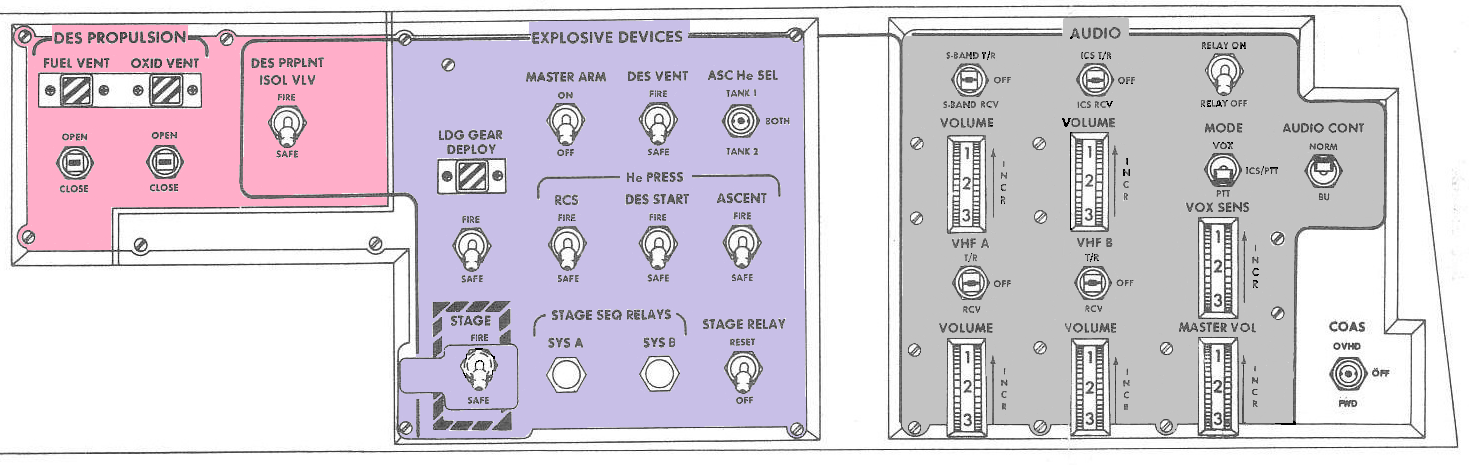
PANEL 8
DES PROPULSION FUEL VENT switch
DES PROPULSION FUEL VENT talkback
DES PROPULSION OXID VENT switch
DES PROPULSION OXID VENT talkback
STAGE SEQ RELAYS SYS A component caution light
STAGE SEQ HELA YS SYS B component caution light
Panel 12
PANEL 14
DC FEEDER FAULT component caution light
BAT FAULT component caution light
POWER/TEMP MON selector switch
BAT 5 NORMAL LMP FEED talkback
BAT 5 BACK UP CDR FEED talk back
BAT 6 NORMAL CDR FEED talkback
BAT 6 BACKUP LMP FEED talkback
ASC PRESS (MPS) - Goes on if pressure in either ascent helium Link drops below 2.773 psia prior to staging or if blanket pressure in fuel or oxidizer lines biopropellant valves drops below 120 psia. Light goes off when deadface switch is actuated by separation of descent and ascent stages, or by resto ration of fuel or oxidizer blanket pressure.
DES REG (MPS) - Goes on if, after pressurization, pressure in descent helium lines downstream of regulators exceeds 260 psia or drops below 220 psia. Light goes off when nominal pressure is restored or when ascent and descent stages are separated.
DES QTY (MPS) - Goes on if, before staging, descent tanks contain propellants for only approximately 2 minutes burn time at hover (25% ) thrust. MASTER ALARM light and tone are inhibited for this warning.
CES AC (GN&CS) - Goes on if a-c voltage in control electronics section of GN& CS is out of tolerance. A-C voltage (28 volts, singlephase; or 26 volts, 800 cps, threephase) is required. Light goes off when GYRO TEST switch is placed in POS HT or NEG HT position.
CES DC (GN&CS) - Goes on if voltage of any d-c power supply in CES is out of tolerance. D-C power supply voltages arc +15, -15, +4. -3 , +6, and -6 volts . Light goes off when GYRO TEST switch is placed in POS HT or NEG HT position.
AGS (GN&CS) - Goes on if any ASA power supply fails or if fail signal is generated by AEA test assembly. Light goes off when 02/H20 Qty MON Switch is momentarily set to C/W RESET. Power supply voltages are 28 and 12 volts dc, and 28 volts. 400 cps. Signal is inhibited when AGS STATIS switch is set to OFF. Thermal switch is in series with 112 vdc. Switch opens at 150 ± 5 °F and closes at 130±5 °F. When ACS STATUS switch is moved from OFF to STB Y, AGS light flashes and MASTEH ALARM goes on. When switch is moved from STBY to OPR, AGS Light goes on, then off and MASTEH ALARM goes off.
LGC (GN&CS) - Goes on if LGC power supplies, counter, or scaler fail. Power supply voltages are +28, +14, or +4 volts dc. Light goes off when nominal voltage is restored or GUID CONT switch is set to AGS.
ISS (GN&CS) - Lights if failure of lMU, PIPA during main engine thrusting, or CDU occurs. Light goes off when GUID CONT switch is set to ACS.
RCS TCA (RCS) - Goes on if GN&CS issues firing command to primary coils of specific thruster, but there is no chamber pressure at that thruster. Goes on if opposing collinear jets are on simultaneously. Light is extinguished when thruster pair isolation valve associated with failed TCA is closed.
RCS A REG (HCS) –Goes on when pressure sensed by pressure transducer downstream of system A pressure regulators exceeds 218 psia or drops below 165 psia. Light is inhibited when SYSTEM A MAIN SOV switch is set to CLOSE.
RCS B REG (HCS) –Goes on when pressure sensed by pressure transducer downstream of system B pressure regulators exceeds 218 psia or drops below 165 psia. Light is inhibited when SYSTEM B MAIN SOV switch is set to CLOSE.
DC BUS (EPS) - Goes on if d-c voltage drops below 26.5 volts on either Commander's or LM Pilot's d-c bus. Light goes off when nominal voltage is restored.
CABIN (ECS) - Goes on if cabin pressure drops below 4.15±0.15 psia. Light goes on when cabin pressure is restored to 4. 8 psia. It does not light during intentional cabin depressurization.
SUIT/ FAN (ECS) - Goes on if pressure within suit I drops below 3.12 psia or if suit circulating fan No. 2 fails. Light goes on when nominal suit pressure is restored.
ASC HI REG (MPS) - Goes on if helium pressure downstream of regulators in ascent helium lines exceeds 220 psia. Goes off when pressure is reduced lo nominal values.
ASC QTY (MPS) - Goes on if fuel or oxidizer in ascent tank is sufficient for only 10-second burn. Signal permits manual shutdown of ascent engine to avoid explosive potential, resulting from depletion of fuel before oxidizer or vice versa. If light goes on, assent engine thrusting is not available for midcourse correction or rendezvous braking.
ENG GMBL (MPS) - Lights if difference between gimbal drive signal and gimbal response from Y-or z-axis trim function is sensed. GDA signal is enabled only when descent engine is armed and is disabled after separation of ascent and descent stages.
INVERTER (EPS) - Goes on if a-c bus voltage is less than 112 volts, or if a-c bus frequency is less than 3 98 cps or exceeds 102 cps. Light goes off when within tolerance conditions are restored or when INVERTER switch is set to OFF.
BATTERY (EPS) - Goes on if overcurrent, reverse current, or overtemperature occurs in any descent or ascent battery. Light goes off when non1inal conditions are restored, or if affected battery is turned off.
RNDZ RDR (GN&CS) - Goes on if RR data-not-good condition occurs. Signal is enabled only when rendezvous radar selector switch is set to AUTO TRACK. Light goes off when data-good condition is restored or RR is turned off.
PRE AMPS (RCS) - Goes on if either of two parallel redundant -4.7-volt d-c regulated power supplies that provide power to RCS jet preamplifiers are out of tolerance. Light goes out when DES BATS SWITCH is set to DEADFACE or ABORT pushbutton is pressed.
ED RELAYS (ED) - Goes on when master arm relay or one of system A or system B stage sequence relays fails. Light goes off when ED LOCIG PWR A or B circuit breakers is opened.
RCS - Goes on if pressure of helium tank in system A or B drops below 1,700 psia. Light goes off when TEMP/PRESS MON switch is set to He.
HEATER - Goes on if out-of-tolerance temperature exists in RCS thruster quad, RR assembly, LR antenna assembly or S-band steerable antenna. Light goes off when TEMP MONITOR switch is set to affected heater position.
C/W PWR (CWEA) - Goes on if any regulated power supply fails. Light goes off when normal power is restored to CWEA. Regulated power: +23, +9, +4, and -3 volts.
ECS - Goes on if glycol pump 1 or 2 fails, CO2 partial pressure exceeds 7. 6 mm Hg, water separator fails, or suit fan No. 1 fails. Light goes off when glycol pump pressure is restored, followed by momentarily setting GLYCOL switch to appropriate pump position; nominal water separator speed is restored; or suit fan No. 2 is selected.
02 QTY (ECS) - Goes on if pressure in descent oxygen tank drops below 135 psia, if less-than-full pressure (less than 684 psia) occurs in either ascent oxygen tank, or if pressure in ascent tank No. l is less than 100 psia.
GLYCOL (ECS) - Goes on if quantity of glycol in primary coolant loop is low or if primary-loop glycol temperature, sensed at glycol water evaporator outlet, exceeds +50° F. Both signals are inhibited after GLYCOL switch is set to INST (SEC) and GLYCOL PUMP SEC circuit breaker (panel 1G) is pressed. If lit due to hightemperature condition, goes off when nominal temperature level is restored.
S-BD RCVR - Goes on if S-band receiver automatic gain control fails. Light is enabled when RANGE FUNCTIONS switch is set to TW/CWEA ENABLE. Light goes off when switch is set to OFF/RESET.
TEMP indicator (RCS) - Indicates propellant temperature (+ 20° to + 120° F) of systems A and B, by measuring fuel tank temperature (with TEMP/PRESS MON selector switch set to PRPLNT). Indicator consists of two dials and vertical movable pointers.
PRESS indicator (HCS) - Indicates pressure (0 to 4,000 psia) of helium tank, helium regulator outlet, and fuel or oxidizer manifolds of systems A and B, as (panel 1G) selected with TEMP/PRESS MON selector switch. Helium tank pressure is obtained by multiplying reading by 10.
PRESS indicator power failure indicator - Red light goes on when power to indicator is interrupted.
QUANTITY indicator (RCS) - Continuously indicates quantity (percentage) of propellant remaining for RCS systems A and B.
QUANTITY indicator power failure indicator - Red light goes on when power to indicator is interrupted.
MISSION TIMER indicator - Displays digital readout of elapsed time in hours, minutes, and seconds. Indicator is controlled with TIMER CONT and SLEW CONT Switches on panel 5. Maximum time displayed is 999 hours 59 minutes and 59 seconds. MIISSION TIMER indicator can only count up. If PCMTE timing pulses fail, an internal tuning fork supplies the 10 pps clock frequency, and a display appears before the first indicator digit.
EVENT TIMER indicator - Displays digital readout of time (0 minutes 0 seconds to 59 minutes 59 seconds). EVENT TIMER is controlled with RESET/COUNT, TIMER CONT, SLEW CONT MIN, and SLEW CONT SEC switches on panel 3. EVENT TIMER\ indicator can count up or down. lf it fails, MISSION TIMER indicator can be used.
X-Pointer indicator – Displays forward and lateral velocities, Lateral velocities only, or rendezvous radar LOS elevation and azimuth angular rates, depending upon setting of RATE/ ERR MON switch and MODE SEL switch. Forward and lateral velocities are coincident with LM Z and Y body axis velocities when PGNS drives display. When LH drives display, forward and lateral velocities arc coincident with LM Z anti Y axis (from hi-gate point to touchdown). When AGS drives display, lateral Y-axis velocity only is displayed. When RR is selected, LOS rates are displayed.
X-Pointer indicator power failure indicator - Red light goes on when power to indicator is interrupted.
LUNAR CONTACT light - Light goes on when landing gear probe touches surface, to indicate that engine should he turned off. Light goes off when either engine stop switch is pressed.
X-POINTER SCALE switch - Controls scale range of X-pointer indicator.
HI MULT - When LOS azimuth and elevation rates are displayed, this position provides a scale of +/- 20 mrad/sec. When horizontal velocities are displayed, this position illuminates the X10 multiplier to provide range of ±200 fps.
LO MULT - When LOS azimuth and elevation rates are displayed, this position provides a range of +/-2 mrad/scc. When horizontal velocities are displayed, this position provides range of +/- 20 fps.
THRUST indicator - Displays descent engine chamber pressure, which corresponds to thrust on ENG scale (left pointer) and manual or LGC thrust commands to the engine on CMD scale (right pointer). Both scales read from 0% to 100%. Automatic or manual throttle commands can be dis played, depending on setting of THR CONT switch. The CMD (right) scale indicates 10% thrust command, even when engine is not firing because indicator input is not the actual thrust command input to engine unless the engine is on, and TTCA is at minimum position.
AUTO mode - (GUID CONT switch is set to PGNS) is sum of thrust commands from LGC and TTCA. TTCA provides a minimum thrust command of 10% at all times: it cannot be set to zero. When THR CONT switch is set to AUTO position and TTCA is at minimum position, LGC commands 10% less than required and is summed with 10% command from TTCA to provide required thrust level. When THR CONT switch is set to MAN, LGC commands are removed and all thrust commands originate from TTCA. Normally, during LGC command authority, both pointers will be aligned. If not, a malfunction exists or manual throttle authority is being introduced to enable smooth transition to full manual control. If manual control is desired, THR CONT switch is set to MAN when CMD Pointer reaches 10%; pointers will then realign. If TTCA control is moved beyond minimum thrust position, LGC commands correspondingly less thrust. It is, therefore, possible in AUTO mode to command more thrust than LGC requires, but not possible to command less.
THRUST indicator power failure indicator - Red light goes on when power to indicator is interrupted.
MAIN PROPULSION QUANTITY - Indicate quantity of propellant remaining in descent tanks. Quantity indicator is operative from 0% to 95%.
OXIDIZER - Displays digital readout of percentage (0% to 95%) of usable oxidizer remaining in descent tank selected with PRPLNT QTY MON switch. Quantity indicator is operative from 0% to 95%.
FUEL - Displays digital readout of percentage (0% to 95%) of usable oxidizer remaining in descent tank selected with PRPLNT QTY MON switch. Quantity indicator is operative from 0% to 95%.
MAIN PROPULSION HELIUM indicator - Displays digital readout of super-critical helium pressure in descent cryogenic storage vessel, pressure in descent ambient helium bottle, and temperature or pressure in ascent helium tanks, as selected with HELIUM MON switch.
TEMP indicator - Indicates fuel and oxidizer bulk temperature (+40° to 100° F) in ascent or descent propellant tanks, as selected with PRPLNT TEMP PRESS MON switch.
PRESS indicator - Indicates fuel and oxidizer pressures (0 to 300 psia) for ascent DISP/ENG or descent propellant sections, as selected with PRESS MON switch.
PRESS indicator power failure indicator - Red light goes on when power to indicator is interrupted.
MASTER ALARM pushbutton/light - Selects inputs for FDAI and X-pointer indicator. When switch is set to LDG RDR/ CMPTR, data input is dependent upon settings of MODE SEL and ATTITUDE MON switches.
RATE/ERR MON switch - Selects inputs for FDAI and X-pointer indicator. When switch is set to LDN RDR/ CMPTR, data input is dependent upon settings of MODE SEL and ATTTITUDE MON switches
RNDZ RADAR - Shaft and trunnion angles from the RR are displayed by pitch and yaw error needles of FDAI; LOS azimuth and elevation rates are displayed on X-Pointer indicator (illuminating LOS AZ and LOS ELEV). When switch is set to LDG RDR/ CMPTR, data input is dependent upon settings of MODE SEL and ATTITUDE MON switches.
LDG RDR/CMPTR - Vehicle attitude errors (PGNS or AGS as selected with ATTITUDE MON switch) are displayed by FDAI error needles. Forward and lateral velocities from the LR (PGNS or AGS as selected with MODE SEL switch) are displayed on the X-pointer indicator (illuminating LAT VEL and FWD VEL). AGS provides only lateral velocity data.
ATTITUDE MONITOR switch - Selects input for FDAI total attitude display and input for attitude error needles during landing.
PGNS – LM total attitude signal, after conditioning by GASTA, are fed to FDAI ball: LGC attitude error signals are fed to FDAI pitch, roll, and yaw error needles
Flight director altitude indicator (FDAI) - Displays total vehicle attitudes, attitude rates and altitude errors, or vehicle altitude, altitude rates, and RR shaft and trunnion angles depending on setting of RATE/ERR MON switch. Setting ATTITUDE MON switch selects PGNS or AGS as source of vehicle total attitude and attitude errors displayed on FDAI. Shaft and trunnion angles arc displayed by pitch and yaw error needles, respectively, when RATE\ERROR M0N switch is set to RNDZ RADAR. Altitude rates displayed are always obtained from CES rate gyro assembly.
Altitude/ range indicator - Displays range/range rate data or altitude/altitude rate data as selected with RNG/ALT M0N switch. Range/range rate data are from RR. Altitude / altitude rate data are from LR, PGNS, or AGS, as selected with MODE SEL switch. When LR data is selected, true altitude and altitude rate data are available from low-gate point to touchdown if LM X-axis is vertical. Before reaching low-gate point, only true altitude data are available from LR. When PGNS or AGS is selected, inertially derived altitude and altitude rate data are available for display.
T/W indicator - Displays instantaneous X-axis acceleration in lunar g units (1 Lunar g 5.23 ft/ sec2). Indicator, a self-contained accelerometer, may be used to provide a gross check of engine perforn1ance, because any given throttle setting provides specific acceleration when the vehicle has given mass.
GUID CONT switch - Selects PGNS or AGS for guidance control mode of LM. Switch is spring loaded to center (lock) position.
PGNS - Provides 800-cps power to activate ACA and TTCA, proportional rate command inputs to LGC from ACA, LGC engine on-off signals, descent engine gimbal trim command outputs from LGC, translation on-off commands from TTCA, enabling signals for primary preamplifiers of ATCA, and applies follow-up signal to AEA. When AGS mode is selected, PGNS remains operational. PGNS data may be displayed if desired.
AGS - Provides 800-cps power to activate ACA and TTCA, proportional rate commands to ATCA from ACA, AGS mode trim command, and enabling- signals to the abort preamplifiers of ATCA.
MODE SEL switch - Selects radar or computer data for display on X-Pointer and altitude/ range indicators. Data from selected source are displayed on appropriate horizontal velocity indicator only when RATE/ ERR MON switches are set to LDG RDR/COMPTR. Data from selected source are displayed on altitude/range indicators only when RNG/ALT MON switch is set to ALT/ALT RT.
LDG RADAR - Radar altitude, altitude rate, and forward and lateral velocity are displayed.
PGNS - LGC-computed altitude, altitude rate, and forward and lateral velocity arc displayed.
AGS - AGS-computed altitude, altitude rate and lateral velocity are displayed.
RNG/ALT MON switch - Selects display legend on altitude/ range indicator and displays RR range/range rate data or LR or computer altitude/altitude rate data.
RNG/RNG RT - RR range and range rate data are displayed on altitude/range indicator.
ALT/ALT RT - Data from source selected with MODE SEL switch are displayed on altitude/range indicator.
RNG/ ALT MON switch - Selects display legend on altitude/ range indicator and displays RR range/range rate data or LR or computer altitude/altitude rate data.
RNG/RNG RT - RR range and range rate data are displayed on altitude/range indicator.
ALT/ALT RT - Data from source selected with MODE SEL switch are displayed on altitude/range indicator.
SHFT/TRUN Ϫ switch - Selects range of RR shaft and trunnion angles to be displayed by FDAI pitch and yaw error needles when either RATE/ERR MON switch is set to RNDZ RADAR.
+/- 50°- Full deflection of FDAI pitch and yaw error needles indicates shaft and trunnion angles of 50° or -50° or greater. Less-than-full-deflection positions of needles are linearly proportional to the sine of the shaft and trunnion angles less than +50° or -50°.
+/- 5° - Full deflection of FDAI pitch and yaw error needles indicates shaft and trunnion angles of 5° or -5° or greater. Less-than-full-deflection positions of needles are linearly proportional to the sine of the shaft and trunnion angles less than +5° or -5°.
RATE SCALE switch - Selects scale factors of roll, pitch, and yaw rate scales of FDAI.
25°/sec - Selects 25° per second full scale for rate scales.
5°/sec - Selects 5° per second full scale for rate scales.
ACA PROP switch - Enables isolation of 28 volts, 800 cps to ACA transducer primary coil. If ACA is disabled, landing mission phase is affected.
ENABLE - Enables normal operation of ACA in proportional rate mode.
DISABLE - Disables ACA proportional rate command capability.
ENG THRUST CONT switches –
THR CONT switch - Permits switching from automatic (LGC) throttle control to manual throttle control.
AUTO - LGC command signals are summed with manual command signals from TTCA selected with MAN THROT switch for descent engine throttle control. TTCA always provides minimum 10% command; it cannot be set below this level. When switch is set to AUTO, THRUST indicator displays LGC command plus 10% fixed bias. Manual throttle commands may be introduced by displacing active TTCA. This causes displayed % THRUST CMD to decrease because only LGC commands plus fixed bias are displayed.
MAN - Interrupts LGC throttle commands insuring that descent engine throttle is fed only by manual throttle command signals. CMD THRUST indicator displays manual throttle commands.
MAIN THROT switch - Selects thrust/translation controller for manual adjustment of descent engine thrust level, if corresponding THROTTLE-JETS control select level is set to THROTTLE. This switch also routes manual throttle commands from controller to DECA.
CDR - Enables Commander's thrust/ translation controller to adjust descent engine thrust level.
SE - Enables LM Pilot's thrust/translation controller to adjust descent engine thrust level.
ENG ARM switch - Provides arn1ing signals to engines. Switch is spring loaded lo center (lock) position. Regardless of switch selling, appropriate engine is armed if ABORT or ABORT STAGE switches are actuated.
ASC - Provides arming signal to enable firing of ascent engine and simultaneously signals LGC that engine is armed.
OFF - Removes arming signal from engine valves and LGC.
DES - Provides arming signal to enable firing descent engine and simultaneously signals LGC that engine is armed.
ATT /TRANSL switch - Selects number of jets for X-axis translation maneuvers. This control can only be used with AGS.
4 JETS - Provides four jets for X-axis translation maneuvers.
2 JETS - Provides two jets for X-axis translation maneuvers.
BAL CPL switch - Selects either balanced pairs of RCS jets in a couple or unbalanced X-axis RCS jets to maintain pitch and roll attitude during ascent engine thrust phase when AGS is in guidance control loop. Used only in conjunction with AGS.
ON - Applies 28 -vdc enable voltage to abort preamplifiers 1, 5, 9, 13. Normally in this position (balanced couples) during initial phases of ascent, for maximum stabilization and control of am· center-of-gravity thrust vector misalignment.
OFF - Removes enable voltage from abort preamplifiers 1, 5, 9, 13.
ASCENT He REG 1 switch - Selects inputs to normally open, latching solenoid-operated helium valve upstream of primary pressure regulator. Switch is spring loaded to center position.
OPEN - Energizes solenoid that drives helium valve to open position. Gray talkback is displayed when valve is open.
Center - Removes solenoid excitation; valve remains in last commanded position.
CLOSE - Energizes solenoid that drives helium valve to closed position. Barber-poll talkback is displayed when valve is closed.
Gray display - Indicates helium primary line solenoid valve controlled by ASCENT He REG 1 switch is open.
Barber-pole display - Indicates helium primary line solenoid valve controlled by ASCENT He REG 1 switch is closed.
ASCENT He REG 2 switch - Selects inputs to normally open latching solenoid-operated helium valve upstream of secondary pressure regulator. Switch is spring loaded to center position.
OPEN - Energizes solenoid that drives helium valve to open position. Gray talkback is displayed when valve is open.
Center - Removes solenoid excitation; valve remains in last commanded position.
CLOSE - Energizes solenoid that drives helium valve to closed position.
Gray display - Indicates helium primary line solenoid valve controlled by ASCENT He REG 2 switch is open.
Barber-pole display - Indicates helium primary line solenoid valve controlled by ASCENT He REG 2 switch is closed.
DESCENT He REG 1 switch - Selects inputs lo normally open, latching solenoid-operated helium valve upstream of primary pressure regulator. Switch is spring loaded to center position.
OPEN - Energizes solenoid that drives helium valve to open position. Gray talkback is display when valve is open.
Center - Removes solenoid excitation; valve remains in last commanded position.
CLOSE - Energizes solenoid that drives helium valve to closed position. Barber-pole talkback is displayed when valve is closed.
Gray displayed - Indicates helium primary line solenoid valve controlled by DESCENT He REG 1 switch is open.
DES 2 - Enables discrete outputs from quantity gaging sensor probes of oxidizer tank No. 2 and fuel tank No. 2 to QUANTITY indicators.
OFF - Removes d-c power from gaging system: quantities are not displayed on QUANTITY indicators
PRPLNT TEMP/PRESS MON switch - Selects inputs to propellant temperature- and pressure-indicating devices from ascent or descent propellant tanks. Switch permits monitoring propellant tank temperatures and pressures.
ASC - Connects output of temperature and pressure sensors in ascent propellant tanks to TEMP and PRESS indicators.
DES 1 - Connects output of temperature and pressure sensors in descent fuel and oxidizer tanks No. 1 to TEMP and PRESS indicators.
DES 2 - Connects output of temperature and pressure sensors m descent fuel and oxidizer tanks No. 2 to TEMP and PRESS indicators.
HELIUM M0N selector switch - Selects inputs to helium indicating device from descent cryogenic storage vessel, from pressure transducer devices in ascent helium tanks, and from pressure transducer in ambient helium bottle. Switch permits monitoring super critical helium pressure of descent cryogenic storage vessel, pressure of ascent helium tanks, and ambient pressure of descent ambient helium bottle.
OFF - Removes power from HELIUM indicator; zeros are displayed.
DES AMB PRESS - Connects output of pressure sensor in descent ambient helium bottle to HELIUM indicator.
DES SUPORT PRESS - Connects output of pressure sensor in descent cryogenic storage vessel to HELIUM indicator.
ASC PRESS 1 - Connects output of pressure sensor in manifold downstream of ascent helium tank No. 1 and upstream of explosive valve to HELIUM indicator.
ASC PRESS 2 - Connects output of pressure sensor in manifold downstream of ascent helium tank No. 2 and upstream of explosive valve to HELIUM indicator.
PANEL 2
SYSTEM A ASC FEED 1 switch - Selects inputs to two Latching solenoid-operated interconnect valves in ascent propellant line, which control flow of propellant from ascent propellant tanks to RCS thruster. Switch is spring loaded to center (lock) position. In the event of RCS malfunction, ascent propulsion section can supply propellant to 8 or 16 TCA's (if LM is experiencing a force in the X-direction). This can be accomplished by setting ASC FEED 1 switch for system A, B, or both to ASC FEED 1 and MAIN SOV switch for system A or B, or both to CLOSE. (ASC FEED 2 switch must be set to ASC FFED 2.)
ASC FEED 1 - Energizes solenoids that drive ascent propellant interconnect valves to open position. Gray talkback is displayed when interconnect valves are open.
Center 1 - Removes solenoid excitation. Interconnect va1vps rcn1ain in last commanded position.
CLOSE 1 - Energizes solenoids that drive ascent propellant interconnect valves to closed position. Barber-pole talkback is displayed when interconnect valves are closed.
Gray display A - Indicates ascent fuel interconnect valves arc open. Both ascent fuel interconnect valves must be open to obtain a gray display.
Barber-pole display A ASC Fuel - Indicates interconnect valves are closed. Barber-pole display can be obtained with only one assent fuel interconnect valve closed.
SYSTEM A ASC FEED 2 switch - Selects inputs to two latching solenoid-operated interconnect valves in ascent propellant line, which control flow of propellant from ascent propellant tanks to RCS thrusters. Switch is spring loaded to center (lock) position. ln event of RCS malfunction, ascent propulsion section can supply propellant to 8 or 16 TCA 's, (if LM 1 is experiencing a force in X-direction). This can be accomplished by setting ASC FEED 2 Switch for system A and B, or both, to ASC FEED 2 and MIAN SOV switch for system A or B, or both to CLOSE. (ASC FEED 1 switch must be set to ASC FEED 1.)
ASC FEED 2 - Energizes solenoids that drive ascent propellant interconnect valves to open position. Gray talkback is displayed when interconnect valve are open.
Center 2 - Removes solenoid excitation. Interconnect valves remain in last commanded position.
CLOSE 2 - Energizes solenoids that drive ascent propellant interconnect valves to closed position. Barber-pole talkback is displayed when interconnect valves are closed.
SYSTEM 1 A ASC OXID talkback - Indicates ascent oxidizer interconnect valves are open. Both ascent oxidizer interconnect valves must be open to obtain a gray display.
Barber-pole display - Indicates interconnect valves arc closed. Barber-pole display can be obtained with only one ascent oxidizer interconnect closed.
SYSTEM A LGC THRUSTER PAIR CMDS QUAD 1 switch
OPEN – Energizes two solenoids that drive isolation valves to open position. Gray talkback is displayed.
Center – Removes Solenoids excitation. Isolation valves remain in the last commanded position.
CLOSE - Energizes two solenoids that drive isolation valves to close and feeds signal to LGC to inhibit automatic operations of TCAs. Barber-pole talkback is displayed.
SYSTEM A LGC THRUSTER PAIR CMDS QUAD 1 talkback (LM 10 and subq) - Indicates enable or disable status of system A quadrant 1 LGC commands.
Gray display - Indicates normal LGC command of system A quadrant 1 jet firing.
Barber-pole display - Indicates LGC command of system A quadrant 1 jet firing is inhibit.
Red display - Indicates system A quadrant 1 TCA failed to fire on LGC command.
SYSTEM A LGC THRUSTER PAIR CMDS QUAD 2 switch
OPEN – Energizes two solenoids that drive isolation valves to open position. Gray talkback is displayed.
Center – Removes Solenoids excitation. Isolation valves remain in the last commanded position.
CLOSE - Energizes two solenoids that drive isolation valves to close and feeds signal to LGC to inhibit automatic operations of TCAs. Barber-pole talkback is displayed.
SYSTEM A LGC THRUSTER PAIR CMDS QUAD 2 talkback - Indicates enable or disable status of system A quadrant 1 LGC commands.
Barber-pole display - Indicates LGC command of system A quadrant 2 jet firing is inhibited.
Red Display - Indicates system A quadrant 2 TCA failed to fire on LGC command.
SYSTEM A LGC THRUSTER PAIR CMDS QUAD 3 switch
OPEN – Energizes two solenoids that drive isolation valves to open position. Gray talkback is displayed.
Center – Removes Solenoids excitation. Isolation valves remain in the last commanded position.
CLOSE - Energizes two solenoids that drive isolation valves to close and feeds signal to LGC to inhibit automatic operations of TCAs. Barber-pole talkback is displayed.
SYSTEM A LGC THRUSTER PAIR CMDS QUAD 3 talkback - Indicates enable or disable status of system A quadrant 3 LGC commands.
Gray display - Indicates normal LGC command of system A quadrant 3 jet firing.
Barber-pole display - Indicates LGC command of system A quadrant jet firing is inhibited.
Red display - indicates system 3 quadrant TCA failed to fire on LGC command.
SYSTEM A LGC THRUSTER PAIR CMDS QUAD 4 switch
OPEN – Energizes two solenoids that drive isolation valves to open position. Gray talkback is displayed.
Center – Removes Solenoids excitation. Isolation valves remain in the last commanded position.
CLOSE - Energizes two solenoids that drive isolation valves to close and feeds signal to LGC to inhibit automatic operations of TCAs. Barber-pole talkback is displayed.
SYSTEM A LGC THRUSTER PAIR CMDS QUAD 4 talkback - Indicates enable or disable status of system A quadrant 4 LGC commands.
Gray display - Indicates normal LGC command of system A quadrant 4 jet firing.
Barber-pole display - Indicates LGC command of system A quadrant 4 jet firing is inhibited.
Red display - Indicates system A quadrant 4 TCA failed to fire on LGC command.
SYSTEM B ASC FEED 1 switch - Selects inputs to two latch-type solenoid-operated interconnect valves in ascent propellant line, which control flow of propellant from ascent propellant tanks to HCS thrusters. Switch is spring loaded to center (lock) position. In event of RCS malfunction, ascent propulsion section can supply propellant to 8 or 16 TCA's. (if LM1 is experiencing a force in the X-direction). This can be accomplished by setting ASC FEED 1 switch for system A or B, or both, to ASC FEED 1 and MAIN SOV switch for system A or B, or both, to CLOSE. (ASC FEED 2 switch must be set to ASC FEED 2.)
ASC FEED 1 - Energizes solenoids that drive ascent propellant interconnect valves to open position. Gray talkback is displayed when interconnect valves are open.
Center - Removes solenoid excitation. Interconnect valves remain in last commanded position.
CLOSE - Energizes solenoids that drive ascent propellant interconnect valves to closed position. Barber-pole talkback is displayed when interconnect valves arc closed.
Gray display - Indicates ascent fuel interconnect valves are open. Both ascent fuel interconnect valves must be open to obtain a gyro display.
Barber-pole display - Indicates interconnect valves are closed. Barber-pole display can he obtained with only one ascent fuel interconnect valve closed.
SYSTEM B ASC FEED 2 switch - Selects inputs to two latch-type solenoid-operated interconnect valves in ascent propellant line, which control flow of propellant from ascent propellant tanks to RCS thrusters. Switch is spring loaded to center (lock) position. In event of RCS malfunction, ascent propulsion section can supply propellant to 8 or 16 TCA's, (if LM is experiencing a force in +X-direction). This can be accomplished by setting ASC: FEED 2 switch for system A or B, or both, to ASC FEED 2 and MAIN SOV switch for system A or B, or both, to CLOSE. (ASC FEED 1 switch must be set to ASC FEED 2.)
ASC FEED 2 - Energizes solenoids that drive ascent propellant interconnect valves to open position. Gray talkback is displayed when interconnect valves are open.
Center - Removes solenoid excitation. Interconnect valves ren1ain in last commanded position.
CLOSE - Energizes solenoids that drive ascent propellant interconnect valves to closed position. Barber-pole talkback is displayed when interconnect valves are closed.
Gray display - Indicates ascent oxidizer interconnect valves are open. Both ascent oxidizer interconnect valves must be open to obtain a gray display.
Barber-pole display - Indicates interconnect valves arc closed. Barber-poll display can be obtained with only one ascent oxidizer interconnect valve closed.
SYSTEM B LGC THRUSTER PAIR CMDS QUAD 1 switch
ENABLE - Permits normal LGC command of system B quadrant 1 jet firing. Gray talkback is displayed.
DISABLE - Provides signal to LGC to inhibit firing commands to system B quadrant 1 jets. Inhibits CWEA and removes TCA-failure indication. Barber-poll talkback is displayed.
SYSTEM B LGC THRUSTER PAIR CMDS QUAD 1 talkback - Indicates enable or disable status of system B quadrant 1 LGC commands.
Gray display - Indicates normal LGC command of system B quadrant 1 jet firing.
Barber-pole display - Indicates LGC command of system B quadrant 1 jet firing is inhibited
Red display - Indicates system B quadrant 1 TCA failed to fire on LGC command.
SYSTEM B LGC THRUSTER PAIR CMDS QUAD 2 switch
ENABLE - Permits normal LGC command of system B quadrant 2 jet firing. Gray talkback is displayed.
DISABLE - Provides signal to LGC to inhibit firing commands to system B quadrant 2 jets. Inhibits CWEA and removes TCA-failure indication. Barber-pole talkback is displayed.
SYSTEM B LGC THRUSTER PAIR CMDS QUAD 2 talkback - Indicates enable or disable status of system B quadrant 2 LGC commands.
Gray display - Indicates normal LGC command of system B quadrant 2 jet firing.
Barber-pole display - Indicates LGC command of system B quadrant 2 jet firing is inhibited.
Red display - Indicates system B quadrant 2 TCA failed to fire on LGC command.
SYSTEM B LGC THRUSTER PAIR CMDS QUAD 3 switch (LM 10 and subq)
ENABLE - Permits normal LGC command of system B quadrant 3 jet firing. Gray talkback is displayed.
DISABLE - Provides signal to LGC to inhibit firing commands to system B quadrant 3 jets. Inhibits CWEA and removes TCA-failure indication. Barber-poll talkback is displayed.
SYSTEM B LGC THRUSTER PAIR CMDS QUAD 3 talkback - Indicates enable or disable status of system B quadrant 3 LGC commands.
Gray display - Indicates normal LGC command of system B quadrant 3 jet firing.
Barber-pole display - Indicates LGC command of system B quadrant 3 jet firing is inhibited
Red display - Indicates system B quadrant 3 TCA failed to fire on LGC command.
SYSTEM B LGC THRUSTER PAIR CMDS QUAD 4 switch (LM 10 and subq)
ENABLE - Permits normal LGC command of system B quadrant 4 jet firing. Gray talkback is displayed.
DISABLE - Provides signal to LGC to inhibit firing commands to system B quadrant 4 jets. Inhibits CWEA and removes TCA-failure indication. Barber-poll talkback is displayed.
SYSTEM B LGC THRUSTER PAIR CMDS QUAD 4 talkback - Indicates enable or disable status of system B quadrant 4 LGC commands.
Gray display - Indicates normal LGC command of system B quadrant 4 jet firing.
Barber-pole display - Indicates LGC command of system B quadrant 4 jet firing is inhibited.
Red display - Indicates system B quadrant 4 TCA failed to fire on LGC command.
Barber-pole display - Indicates propellant main shutoff valves are closed. Both main shutoff valves must be closed to obtain barber-pole display.
(MAIN SOV) Crossfeed Switch – Selects Input to two latching, solenoid-operated fuel and oxidizer crossfeed valves in crossfeed piping arrangement between systems A and B. Switch is spring loaded to center (lock) position. If system A or B Malfunctions, the related MAIN SOV switch is set to CLOSE, and CROSSFEED switch is set to OPEN. This opens crossfeed valves open and permits fuel and oxidizer to flow from operative system to thrust chambers of both systems. CRSFD talkback displays status of crossfeed valves.
Open – Energizes two solenoids that open crossfeed valves. Gray talkback is displayed when crossfeed valves are open.
Center – Removes solenoid excitation. Crossfeed valves remain in last commanded position.
Close – Barber-Pole Talkback is displayed when crossfeed valves are closed.
Crossfeed Talkback
Gray Display – Indicates fuel and oxidizer crossfeed valves controlled by CRSFD switch are open. Both crossfeed valves must be open to display a gray display.
Barber –pole Display - Indicates fuel and oxidizer crossfeed valves are closed. Barber-pole can be obtained with only one crossfeed valve closed.
June 21
TEMP/PRESS MON selector switch – Selects input to propellant temperature and pressure indicating devices for Systems A and B. Switch permits monitoring
MAIN SOV SYS A/B switch - Selects inputs to two latching solenoid-operated, main shutoff valves in propellant lines downstream of propellant tanks. Switch is spring loaded to center (lock) position. These valves are normally open. If system A or B malfunctions, propellant flow to malfunctioning system is interrupted by setting corresponding switch to CLOSE.
OPEN - Energizes solenoids that drive propellant main shutoff valves to open position. Gray talkback is displayed when main shutoff valves are open.
Center - Removes solenoid excitation. Main shutoff valves remain in last commanded position.
CLOSE - Energizes solenoids that drive propellant main shutoff valves to closed position. Barber-pole talkback is displayed when main shutoff valves are closed.
Gray display - Indicates propellant main shutoff valves controlled by SYSTEM MAIN SOV switch are open. A gray display can be obtained with only on" main shutoff valve open.
Barber-pole display - Indicates main propellant shutoff valves arc closed. Both main shutoff valves must be closed to obtain a barber-pole display.
ACA PROP switch - Enables isolation of 28 volts, 800 cps to ACA transducer primary coil. If ACA is disabled, only the landing mission phase is affected.
ENABLE - Enables normal operation of ACA in proportional rate mode.
DISABLE - Disables ACA proportional rate command capability.
THR CONT switch - Permits switching from automatic (LGC) throttle control to manual throttle control.
AUTO - LGC command signals are summed with manual command signals from TTCA selected with M\IAN THROT switch for descent engine throttle control. TTCA always provides minimum 10% command; it cannot be set below this level. When switch is set to AUTO, THRUST indicator displays LGC command plus 10% fixed bias. Manual throttle commands may be introduced by displacing active TTCA. This causes displayed % THRUST CMD to decrease because only LGC commands plus fixed bias are displayed.
MAN - Interrupts LGC throttle commands insuring that descent engine throttle is fed only by manual throttle command signals. CMD THRUST indicator displays manual throttle commands.
MAN THROT switch - Selects thrust/translation controller for manual adjustment of descent engine thrust level, if corresponding THROTTLE-JETS control select level is set to THROTTLE. This switch also routes manual throttle commands from controller to DECA.
CDR - Enables Commander's thrust/ translation controller to adjust descent engine thrust level.
SE - Enables LM Pilot's thrust/translation controller to adjust descent engine thrust level.
ENG ARM switch - Provides arming signals to engines. Switch is spring loaded to center (lock) position. Regardless of switch selling, appropriate engine is armed if ABORT or ABORT STAGE switches are actuated.
ASC - Provides arming signal to enable firing of ascent engine and simultaneously signals LGC that engine is armed.
OFF - Removes arming signal from engine valves and LGC.
DES - Provides arming signal to enable firing descent engine and simultaneously signals LGC that engine is armed.
ATT /TRANSL switch
ENVR0NMENTAL CONTROL
SUIT ° F scale - Displays suit circuit temperature (degrees Fahrenheit) sensed at suit outlet.
CABIN ° F scale - Displays cabin interior temperature (degrees Fahrenheit) sensed at cabin fan inlet.
SUIT PSIA scale - Displays suit circuit pressure (psia) sensed downstream of suit gas supply connectors.
CABIN PSIA scale - Displays cabin interior pressure (psia) sensed by aneroid sensor on cabin pressure sensor switch.
Press indicator power failure indicator Light - Red light goes on when power to indicator is interrupted.
PART PRESS CO2 indicator - Displays partial pressure of carbon dioxide content of gas in ARS.
TEMP scale - Displays glycol temperature (degrees Fahrenheit) in primary coolant loop. However, following failure of primary loop and selection of secondary coolant pump, with GLYCOL selector switch and plays glycol pump discharge pressure (psia) in primary coolant loop. However, following failure of primary loop and selection of secondary coolant pump with GLYCOL selector switch and GLYCOL PUMP SEC circuit breaker, indicator displays secondary glycol pump discharge pressure.
GLYCOL PUMP SEC circuit breaker indicator displays secondary coolant loop temperature.
PRESS scale - Displays glycol pump discharge pressure (psia) in primary coolant loop. However, following failure of primary loop and selection of secondary coolant pump with GLYCOL selector switch and GLYCOL PUMP SEC circuit breaker, indicator displays secondary glycol pump discharge pressure.
GLYCOL indicator power failure indicator - Red light goes on when power to indicator is interrupted.
02 scale - Displays quantity of oxygen (percent) remaining in descent oxygen tank or either ascent oxygen tank, as selected with 02 H20 QTY MON switch.
H20 scale - Displays quantity of water (percent) remaining in descent water tank or either ascent water tank, as selected with 02 H20 QTY MON switch.
QUANTITY indicator power failure indicator - Red light goes on when power to indicator is interrupted.
X-Pointer indicator - Displays forward and lateral velocities, lateral velocities only, or rendezvous radar LOS elevation and azimuth angular rates, depending upon setting of RATE/ERR MION switch and MODE SEL switch. Forward and lateral velocities arc coincident with LM Z and Y body axis velocities when PGNS drives display. When LH drives display, forward and lateral velocities are coincident with LM Z and Y axis (from hi-gate point lo touch-down). When AGS drives display, lateral Y -axis velocity only is displayed. When RR is selected, LOS rates are displayed.
X-Pointer indicator power failure indicator - Red light goes on when power to indicator is interrupted.
Flight director attitude indicator (FDAI) - Displays total vehicle attitudes, attitude rates and attitude errors, or vehicle attitude, altitude rates, and RR shaft and trunnion angles, depending on setting of RATE/ERR MON switch. Setting ATTITUDE MON switch selects PGNS or AGS as source of vehicle total attitude and attitude errors displayed on FDAI. Shaft and trunnion angles are displayed by pitch and yaw error needles, respectively, when RATE/ERR MON switch is set to RNDZ RADAR. Attitude rates displayed are always obtained from CES rate gyro assembly.
MASTER ALARM pushbutton/light - Light flashes when any caution or warning light goes on, except C/W PWR caution and DES QTY warning lights. Pressing Commander's or LM Pilot's pushbutton extinguishes both MASTER ALARM lights and terminates audible tone, but has no effect on caution or warning light(s).
Audible tone - Initiated in conjunction with MASTER ALARM pushbutton/light and caution/warning array light(s).
RATE/ERR MON switch - Selects inputs for FDAI and X-pointer indicator. When switch is set to LDG RDH/ CMPTH, data input is dependent upon settings of MODE SEL and ATT ITUDE MON switches.
RNDZ RADAR - Shaft and trunnion angles from the RR are displayed by pitch and yaw error needles of FDAI; LOS azimuth and elevation rates are displayed on X-pointer indicator (illuminating LOS AZ and LOS ELEV).
LDG RDR/COMPTR - Vehicle attitude errors (PGNS or AGS as selected with ATTITUDE M0N switch), are displayed by FDAI error needles. Forward and lateral velocities from the LR (PGNS or AGS as selected with MODE SEL switch) are displayed on the X-pointer indicator (illuminating LAT VEL and FWD VEL). AGS provides only lateral velocity data.
ATTITUDE MON switch - Selects input for FDAI total attitude display and input for attitude error needles during landing.
PGNS - LM total attitude signals, after conditioning by GASTA, are fed to FDAI ball; LGC attitude error signals are fed to FDAI pitch, roll, and yaw error needles.
AGS - AGS LM total attitude signals are fed to FDAI ball; AGS attitude error signals are fed to FDAI pitch, roll, and yaw error needles.
GLYCOL selector switch - Selects either circulating pump in primary coolant loop or circulating pump in secondary coolant loop. Pump failure causes GLYCOL component caution light and ECS caution light to go on.
PUMP 1 - Activates glycol pump No. 1. GLYCOL component caution light and F.CS caution light go off when glycol pump No. 2 is activated.
PUMP 2 - Activates glycol pump No. 2.
INST (SEC) - Activates glycol instrumentation. If glycol pump No. 2 fails, both lights will go on. Pressing ECS: GLYCOL PUMP SEC circuit breaker activates secondary glycol pump and extinguishing ECS caution light.
GLYCOL component caution light - Goes on to indicate failure of active glycol pump. Light goes out when pump is reselected and normal pressure is restored.
SUIT FAN selector switch - Selects suit fan to circulate breathing oxygen in suit circuit. Failure of suit fan No. 1 causes SUIT FAN component caution light and ECS caution 1 light to go on. Selection of fan No. 2 and return of normal ΔP across the fans, extinguishes both lights.
OFF - Shuts off all power to suit fans.
1 - Selects fan No. 1 for operation.
2 - Selects fan No. 2 for operation.
SUIT FAN component caution light - Lights to indicate low ΔP across suit fan assembly, due to malfunction of operating suit fan. Light goes off when SUIT FAN switch is set to other fan. However, light goes on if newly selected fan does not develop proper ΔP within approximately 25 seconds, or when failure occurs in selected fan.
CO2 component caution light - Goes on to indicate that CO2 partial pressure in suit circuit exceeds 7. G mm Hg or if C02 CANISTER SEL valve ls set to SEC. Light goes off when primary canister ls replaced with unsaturated canister. C02 CANISTER SEL valve is set to PRIM and CO2 partial pressure is restored lo within tolerance condition.
H20 SEP component caution light - Goes on to indicate low-speed condition or failure (stoppage) ln selected water separator. Light goes off when other water separator is selected with H2O SEP SEL valve and water separator comes up to desired speed.
02/H20 QTY MON selector switch - Selects, for monitoring on QUANTITY indicator, quantities remaining in descent or ascent oxygen and water storage tanks.
C/W RESET - Routes signal to CWEA to extinguish O2 QTY caution light, WATER QTY caution light or AGS warning Light if on.
DES 1 - Descent oxygen tank No. 1 pressure is displayed on 02 QUANTITY indicator and quantity remaining in descent water tank No. 1 is displayed on H20 QUANTITY indicator.
DES 2 - Descent oxygen tank No. 2 pressure is displayed on 02 QUANTITY indicator and quantity remaining in descent water tank No. 2 is displayed on H20 QUANTITY indicator.
ASC 1 - Ascent oxygen tank No. 1 pressure is displayed on 02 QUANTITY indictor and quantity remaining in ascent water tank No. 1 is displayed on H20 QUANTITY indicator.
ASC 2 - Ascent oxygen tank No. 2 pressure is displayed on O2 QUANTITY indicator and quantity remaining in ascent water tank No. 2 displayed on H20 QUANTITY indicator.
655
ENG GIMBLE switch - Enables or disables engine gimbal drive capability. Normally set to ENABLE. If ENG GMBL caution light goes on, astronaut must set switch to OFF.
ENABLE - Gimbal trim signals are enabled to displace descent engine along Y and Z axes.
OFF - Power to the GDA's is removed, disabling the gimbal drive capability.
DES ENG CMD 0VRD switch - Supplies alternate source of 28-vdc to descent engine shut-off valves. Switch is utilized to keep valves open if DECA power fails.
ON - Applies 28 vdc to descent engine shut-off valves. Circuit is completed through normally closed contacts of ABORT STAGE switch.
OFF - Removes 28 vdc from valves.
AUTO - Enables LGC to position LH antenna as function of mission phase.
DES - Drives antenna to first position used before hover point. Because antenna cannot be driven to its first position by LGC and it is necessary to check out completely two-position capability and provide override of position drive signal if I.R antenna interface fails, DES and HOVER positions are used.
HOVER - Drives antenna to its second position for final landing phase.
SIGNAL STRENGTH indicator - Displays LR and RR data for test and flight operations, respectively, as selected with TEST, MONITOR switch.
RENDEZVOUS RADAR NO TRACK light - Light goes on to indicate that RR has broken track (data not good) in any one of three tracking modes.
RADAR TEST Switch - Provides testing capability of both radars.
RNDZ - Initiates test circuitry. RR performance is checked by monitoring SIGNAL STRENGTH indicator after appropriate setting of TEST I MONITOR switch. In this test mode, altitude/range meter displays appropriate test value.
OFF - Disables testing capability.
LDG - Initiates test circuitry. LR performance is checked by monitoring SIGNAL STRENGTH indicator after appropriate setting of TEST/MONITOR switch.
TEST /MONITOR selector switch - Select s LR or RR test data or flight performance data for monitoring on SIGNAL STRENGTH indicator.
ALT XMTR - Provides altitude range transmitter power output for display on SIGNAL STRENGTH indicator during test and flight operations.
VEL XMTR - Provides velocity transmitter power output for display on SIGNAL STRENGTH indicator during test and flight operations.
AGC - Provides AGC during RR testing. Specific value of receiver signal strength should be displayed on SIGNAL STRENGTH indicator; however, during flight operations signal varies.
XMTR PWR - Provides specific value of transmitter power output for display on SIGNAL STRENGTH indicator during night operations.
SHAFT ERR - During test, shaft angle error signals are displayed as needle fluctuations with equal amplitude on SIGNAL STRENGTH indicator. During flight operations, these error signals are displayed as needle fluctuations, usually of unequal amplitude, that represent smoothness of servo tracking.
TRUN ERR - Same as for SHAFT ERR position, except trunnion angle errors are displayed.
SLEW RATE switch - Provides two rates for manually slewing radar antenna with SLEW switch.
HI - Selects high slew rate for quick coarse adjustments to guide antenna in direction of target. High slew rate is 7°/sec.
LO - Selects low slew rate for accurately peaking SIGNAL STRENGTH indicator, enabling subsequent initiation of auto track through rendezvous radar mode selector switch with assurance that main lobe lock will be achieved. Low slew rate is 1.33°/sec.
SLEW switch - Slews trunnion or shaft servos, or both, positioning RR antenna for manual acquisition of target and subsequent automatic tracking. Two antenna slew rates are available using SLEW RATE switch. Target acquisition is determined from SIGNAL STRENGTH indicator and auto track mode is enabled with rendezvous radar mode selector switch.
UP - Slews shaft servos to up position, positioning RR antenna for manual acquisition of target and subsequent automatic tracking. RR antenna alignment along LM axis can be determined from FDAI pitch and yaw error needles when RATE/ERR MON switch is set to RNDZ RADAR.
RIGHT - Same as for UP position, except that slewing is to right position.
DOWN - Same as for UP position, except that slewing is to down position.
LEFT - Same as for UP position, except that slewing is to left position.
RENDEZVOUS RADAR mode selector switch - Enables control of RR antenna drive.
AUTO TRACK - Maintains track by comparing received radar signals from three channels; errors are used to drive radar servos.
SLEW - Enables manual control of RR antenna drive with SLEW switch.
LGC - LGC automatically drives antenna towards target. Once target is acquired, radar automatically maintains track and NO TRACK light goes off.
DEAD BAND switch - Switch is not functional when PGNS is in use.
MAX - Provides large-amplitude limit N/A cycle for attitude control system, to conserve RCS fuel during coasting flight. For maximum deadband, which is 5°, FDAI error needle scaling; is +14.4°
MIN - Provides narrow deadband for periods during which accurate manual control is required. During 1nain engine thrusting, minimum deadband is always operating. For minimun1 dcadband, which is 3°, FDAI error needle scaling is 1.7°.
GYRO TEST ROLL switch - Switch is associated with GYRO TEST POS RT switch.
ROLL - Selects FDAI rate gyro to be tested in roll axis.
PITCH - Selects FDAI rate gyro to be tested in pitch axis.
YAW - Selects FDAI rate gyro to be tested in yaw axis.
GYRO TEST POS RT switch - Enables test signal to be applied to N/A rate gyro selected with GYRO TEST ROLL switch.
POS RT - Selected rate gyro output displaces FDAI rate needles and indicates 5°/ second vehicle attitude rate.
OFF - No test signal is produced.
NEG RT - Produces effects opposite to those of POS RT position.
ATTITUDE CONTROL ROLL, PITCH, and YAW switches - Used in conjunction with MODE CONTROL switches to establish attitude control in roll, pitch, and yaw. Normally these switches are set to MODE CONT while PGNS is in control.
MODE CONT - Enables use of proportional mode of ACA when MODE control selector Switch is set to ATT HOLD and PGNS is controlling. When MODE CONTROL selector switch is set to AUTO, LGC supplies attitude commands to maneuver LM. Under AGS control, function of MODE CONT positions are the same manner as when PGNS is controlling.
PULSE - Under PGNS control this position is inoperative. Under AGS control, the PULSE and DIR positions differ only in how RCS thrusters fire. When PULSE is selected, two jets in selected axis fire al constant pulsed rate as long as ACA is displaced more than one-fourth of full throw. PULSE and DIR positions provide open loop acceleration. Hales produced must be nulled to zero by inducing opposite acceleration command. Attitude is not maintained automatically until switch is returned to MODE CONT.
DIR - Under PGNS control, when MODE CONTROL selector switch is set to ATT HOLD or AUTO, DIR mode can be used in any axis. Each switch must be set to DIR independently. Displacing ACA one-fourth of full throw causes continuous two-jet firing for selected axes. As in PULSE position, open loop acceleration is provided; it must be nulled in as during pulse operation .
PGNS MODE CONTROL switch - Affects outputs of ACA's, TTCA's and LGC. Switch is associated with ATTITUDE CONTROL switches and GUID CONT switch.
OFF - Establishes the following conditions: (a) Limits operation of the ACA's to the hardover position. (b) Enables two-get direct attitude control in axis, selected with ATTITUDE CONTROL switches. (c) Disables translation outputs of TTCA's and LGC attitude commands. TTCA throttle commands are not affected. LGC engine-off signals are not enabled; engine must be manually turned off.
ATT HOLD - In this mode, astronauts can command angular rates proportional to displacement of ACA' s. Mode is functional with either PGNS or AGS controlling operation. When ACA is out of detent, ATTITUDE CONTROL switches set to MODE CONT, and LGC not in control, attitude loops are opened and axis transducers are compared to rate gyro outputs to provide proportional commands. While maneuvering, attitude synchronizers follow as attitude changes. If PGNS control is selected, astronauts can command attitude rates proportional to ACA displacement, and attitude is held when ACA is returned to detent. When a programmed minimum impulse mode command (entered via DSKY) is in effect, moving ACA out of detent in any axis commands a pulse to applicable RCS jets. No attitude or attitude rate stabilization is provided in this mode.
Auto – When GUID CONT switch is set to PGNS, rate-compensated steering errors are generated by LGC and on-off commands are fed to jet drivers. RCS translation outputs of TTCA’s are enabled. TTCA and ACA hardover outputs are not affected. When one or more ATTITUDE CONTROL switches are set to PULSE or DIR, the following attitude command capabilities and limitations result. With GUID CONT switch set to PGNS and one or more ATTITUDE CONTROL switches set to DIR, conflicting commands from LGC result when ACA’s are displaced one-fourth of full throw.
AGS MODE CONTROL switch – Affects output of ACA’s, TTCA’s, and LGC. Switch is associated with ATTITUDE CONTROL switches and GUID CONT switch.
OFF – Affects outputs of ACA’s, TTCA’s and LGC. Establishes the following conditions: (a) Limits operations of the ACA’s to the hardover position. (b) Enables two-jet direct attitude control in axis, selected with ATTITUDE CONTROL switches. (c) Disables translation outputs of TTCA's and LGC attitude commands. Switch is associated with ATTITUDE CONTROL switches and GUID CONT switch. TTCA throttle commands are not affected. AGS engine-off signals are not enabled, engine must be manually turned off.
ATT HOLD - In this mode, astronauts can command angular rates proportional to displacement of ACA's. Mode is functional with either PGNS or AGS controlling operation. When ACA is out of detent, ATTITUDE CONTROL switches set to MODE CONT, and AGS in control, attitude loops are opened and axis transducers are compared to rate gyro outputs to provide proportional commands. While maneuvering, attitude synchronizers follow as attitude changes. When ATTITUDE CONTROL switches are set to PULSE or DIR, following attitude command capabilities result: With GUID CONT switch set to AGS, proportional rate commands are disabled for those axes for which PULSE or DIR was selected. With GUID CONT switch set to PGNS and one or more ATTITUDE CONTROL switches set to PULSE, attitude hold mode is not affected. With GUID CONT switch set to PGNS and one or more ATTITUDE CONTROL switches set to DIR, ACA displacement of one-fourth of full throw causes continuous two-jet firing for selected axes, without rate feedback interfering with LGC command signals .
AUTO - With GUID CONT switch set to AGS, attitude error signals are sent to CES from AGS. In CES, these attitude error signals are passed through limiter, which limits angular rate and combines error signals with rate gyro damping signal. Resultant signals control firing of RCS jets through selectable deadband, logic, pulse modulators, and jet driver amplifiers. Rate commands from ACA remain active in this mode; attitude disturbances occur if ACA is displaced inadvertently. TTCA and ACA hardover outputs are not affected. When one or more ATTITUDE CONTROL switches are set to PULSE or DIR, the following attitude command capabilities and limitations result. With GUID CONT switch set to AGS, proportional rate commands are disabled for those axes for which PULSE or DIR was selected.
TENS - Slews tens-column digit of MIN columns at rate of two digits per second as long as switch is held in this position.
Center - Disables slewing function.
UNITS - Slews units-column digit of MIN columns at rate of two digits per second as long as switch is held in this position.
EVENT TIMER SLEW CONT SEC switch - Provides slewing function for EVENT TIMER indicator. Switch is spring loaded to center.
TENS - Slews tens-column digit of SEC columns at rate of two digits per second as long as switch is held in this position.
Center - Disables slewing function.
UNITS - Slews units-column digit of SEC columns at rate of two digits per second as long as switch is held in this position.
RCS SYS A/B-2 QUAD 1, QUAD 2, QUAD 3, and QUAD 4 heater switches - Control the system 2 heaters (redundant heating system) within applicable quad of RCS TCA 's. Heating system 1 provides continuous automatic control of RCS bus engine temperatures. This system has no override capability. When QUAD switches are set to AUTO, engine injector temperatures are maintained at approximately 140°F. If temperature of any quad exceeds +190°F or falls below +190°F, HEATER caution light goes on.
SIDE PANELS switch - Permits control of lighting on LM Pilot's side panels, independently of lighting of forward panel. Enables on/off control of LM Pilot's side panel integral lights.
ON - Connects side panel integral lights to INTEGRAL OVERRIDE switch and INTEGRAL control on panel 5.
OFF - Disconnects side panel integral lights from INTEGRAL control and INTEGRAL OVERRIDE switch on panel 5.
FLOOD OVHD/FWD switch - Energizes crew compartment floodlights. Floodlight power source is independent of that used for integral lighting.
ALL - Energizes all floodlights.
OFF – De-energizes all floodlights.
OVHD/FWD - Energizes two overhead and two forward floodlights. Overhead floodlights are fitted with rotatable reflectors.
FLOOD OVHD/FWD control – Controls the brightness of the LM Pilot's overhead and forward floodlights. Control operates only when FLOOD OVHD/FWD switch is set to OVHD/FWD or ALL, and the overhead hatch is closed. If overhead hatch is open, FLOOD OVHD/FWD switch is bypassed and FLOOD OVHD/FWD control enabled.
DIM to BRIGHT - Controls intensity level of floodlights continuously from dim to bright.
LAMP/TONE TEST selector switch - Performs test as indicated below.
OFF - All test functions are inactive. OFF position is at each end of switching sequence to permit setting switch to OFF without recycling through all test positions.
ALARM/TONE - Tests lamps in MASTER ALARM pushbuttons, and tests audible warning tone.
C/W 1 - Tests lamps in first bank of warning lights on panel 1.
ENG PB-C/W 2 - Tests lamps in engine START and STOP lights and in second bank of warning lights on paneI 1.
C/W 3 - Tests lamps in first bank of caution lights on panel 2.
C/W 4 - Tests lamps in second bank of caution lights on panel 2.
COMPNT - Tests lamps in component caution and lunar contact lights.
EXTERIOR LTG switch - Controls docking and tracking lights.
DOCK - Energizes docking lights.
OFF - Deenergizes docking and tracking lights.
TRACK - Energizes tracking light to full (100%) brightness.
LUNAR CONTACT light - Both lights (red) go on when probe(s) on landing gear touches lunar surface, to indicate that descent engine should be turned off. Light goes off when either engine stop switch is pressed.
X-POINTER SCALE switch - Controls scale range of X-pointer indicator.
HI MULT - When LOS azimuth and elevation rates are displayed, this position provides a scale of +20 mrad/sec. When horizontal velocities are displayed, this position illuminates the X10 multiplier to provide range of +200 fps.
LO MULT - When LOS azimuth and elevation rates are displayed, this position illuminates the X.1 multiplier to provide a range of 2 mrad/sec. When horizontal velolcitics are displayed, this position provides range of +/-20 fps .
ACA/4 JET switch (CDR and LMP) - Enables isolation of 28 volts dc if short occurs in ACA. The nominal position of this switch is ENABLE .
ENABLE - Enables normal operation of TTCA.
DISABLE - Disables four-jet direct attitude control function (hardover position) of ACA.
TTCA/TRANSL switch (CDR and LMP) - Enables isolation of 28 volts dc if short occurs in TTCA. The nominal position of this switch short occurs in ENABLE.
ENABLE - Enables normal operation of TTCA.
DISABLE - Disables translation control function of TTCA.
UPLINK ACTY condition indicator (white) - Indicates that uplink is being received by LGC. Is energized by first character of digital uplink message received by LGC. If light is not turned off by end of uplink transmission, the astronaut should extinguish light when transmission is complete by pressing RSET pushbutton.
TEMP condition indicator (yellow) - Indicates that stable member temperature has exceeded its limits by ±4° F. (Nominal operating temperature +130. 3 °F).
NO ATT condition indicator (white) - Indicates that ISS is not suitable for N/A use as attitude reference. Indicator lamp goes on when LGC is in operate mode and there is no inertial reference, during coarse align, if ISS is off, or IMU is caged.
GIMBAL LOCK condition indicator (yellow) - Indicates that middle gimbal has N/A driven through angle greater than +70° or -70° from its zero position. When middle gimbal angle exceeds +85° or -85° from its zero position, LGC automatically commands coarse align mode in ISS to prevent gimbal oscillation. NO ATT condition indicator goes on.
STBY condition indicator (white) - Indicates that LGC is in standby N/A condition. Indicator lamp is deenergized if LGC is in operate mode.
PROG condition indicator (yellow) - Indicates that program check has failed. Indicator is controlled by computer program.
KEY REL condition indicator (white) - Indicates that internal program has attempted to use DSKY and found it busy due to independent operator action. Indicator is modulated by flash signal.
RESTART condition indicator (yellow) - Indicates one or more of the following abnormal operations: Word has been transferred incorrectly from memory-parity fail. LGC is in endless control loop-TC trap. LGC has been interrupted for 30 msec - RUPT lock. Alarm has been generated by program control. LGC fails to process new job within a period from .64 to 1. 92 seconds.
OPR ERR condition indicator (white) - Indicates that astronaut has performed an improper sequence on the DSKY. Goes out when RESET pushbutton is pressed.
TRACKER condition indicator (yellow) - Indicates RR CDU failure or improper data from RR or LR. When RR or LR are on, indicator lamp is energized if: RR CDU fine error greater than 1. 0 vrms occurs. HH CDU course error greater than 2. 5 vrms occurs. RH read counter limit cycles at rate greater than 160 cps. RH CDU analog-to-digital conversion tails. RH CDU +14-vdc supply decreases to 50% of nominal. RR data-not-good discrete occurs during LGC data read sequence. LR altitude data-not-good discrete or LR velocity data-not-good discrete occurs during LGC data read sequence.
ALT light (yellow) - Indicates altitude data-good signal from LR is absent during Landing Radar Data Read Routine. A flashing light indicates that LGC received data-good signal, but data docs not pass LGC Reasonableness Test.
VEL light (yellow) - Indicates velocity data-good signal from LR is absent during Landing Radar Data Read Routine.
COMPTR ACTY condition indicator (white) - Indicates tl1at LGC is in program other than dummy job (LGC is processing data.)
PROG display indicator - Indicates the program that is being N/A processed LGC.
VERB display indicator - Indicates verb code entered at key-board or commanded by LGC.
NOUN display indicator - Indicates noun code entered at key-board or commanded by LGC.
Data display registers - Indicate numerical data entered at keyboard or commanded by LGC. Sign is associated only with decimal data.
VERB pushbutton (momentary) - Conditions LGC to interpret next two numerical characters as verb code and extinguishes verb numerical display.
NOUN pushbutton (momentary) - Conditions LGC to interpret next N/A two numerical characters as noun code and extinguishes noun numerical display.
CLR pushbutton (momentary) - Used during data loading to blank data register being used; loading can then be resumed. First component load verbs are cleared by pressing CLR pushbutton once. Second and third component load verbs are cleared by ' pressing the pushbutton twice or three times, as required. The data registers clear in H3, R2, R1 order. Refer to paragraph 2.2.3.1.3.
PRO pushbutton (momentary) - Commands LGC to proceed without data. Also commands LGC to enter standby mode if pressed when program P06 is in progress.
KEY REL pushbutton (momentary) - Operator should release DSKY by pressing pushbutton when he is temporarily finished with DSKY.
ENTR pushbutton (momentary) - Informs LGC that assembled data are complete and that requested information is to be executed. Used in two ways: to execute the VERB/ NOUN code appearing on the VERB and NOUN display and to accept data just loaded and appearing in data display registers (Rl, R2, R3).
RSET pushbutton (momentary) - Turns off DSKY condition indicator after condition has been corrected.
0 through 9 pushbuttons (momentary) - Enter numerical data, noun codes, and verb codes into DSKY displays.
+ and - pushbutton (momentary) - Inform LGC that following numerical data are decimal and indicate sign of data.
PR 10 DISP light - Indicates that system has a priority display to bring to the attention of the astronaut.
NO DAP light - Indicates that the DAP is not controlling vehicle attitude.
DES RATE switch - Permits establishing LM rate of descent under PGNS control in fixed increments. Each switch actuation provides a discrete pulse, changing the rate of descent by 1 fps. Response to switch commands is monitored on the altitude rate scale of the Range/Range Rate; Alt/Alt Rate indicator.
+ 1 FPS - Plus sign denotes increase in engine thrust.
Center – Removes power to and resets switch to make system ready to accept the next commanded pulse.
- 1 FPS - Minus sign denotes decrease in engine thrust.
Engine stop pushbutton - Provides discrete stop signals to descent and ascent engines, independent of setting of ENG AHI\1 switch, except when in abort sequence. When pressed, pushbutton remains pressed and illuminated (red). It is reset by pressing- it again.
Engine START pushbutton - Permits immediate manual firing of descent or ascent engine, depending upon setting of ENG ARM switch. When pressed, pushbutton remains pressed and illuminated (red). Actuation of either engine stop pushbutton interrupts override function, the engine stops, and the STAHT pushbutton light goes out.
+X TRANSL pushbutton (momentary) - When held pressed, switch provides four-jet translation in +X-direction by energizing RCS direct (secondary) coils. Upon release of pushbutton, signal is removed from coils, terminating jet firings. If switch fails closed, circuit breaker must be opened. The secondary coils of the RCS engines will be disabled, resulting in loss of hardover and direct modes.
TIMER CONT switch - Provides discrete signals to MISSION TIIIIER indicator.
START - Enables indicator to count upward from number preset with SLEW CONT switches.
STOP - Stops and holds indicator count until START or RESET is selected.
RESET - Resets indicator to zero.
SLEW CONT HOURS switch - Provides slewing function for HOURS columns of MISSION TIMER indicator.
TENS - Slews tens-column digit of HOURS columns at rate of two digits per second as long as switch is held in this position. Hundreds-column digit of HOURS columns is also controlled by the tens position, at rate of one digit per 5 seconds.
Center - Disables slewing function. All digits change in increasing direction.
UNITS - Slews units-column digit of HOURS columns at rate of two digits per second as long as switch is held in this position.
SLEW CONT MIN switch - Provides slewing function for MIN columns of MISSION TIMER indicator. All digits change in increasing direction.
TENS - Slews tens-column digit of MIN columns at rate of two digits per second as long as switch is held in this position.
Center - Disables slewing function.
UNITS - Slews units-column digit of MIN columns at rate of two digits per second as long as switch is held in this position.
SLEW CONT SEC switch - Selects inputs to MISSION TIMER indicator.
TENS - Slews tens-column digit of SEC columns at rate of two digits per second as long as switch is held in this position.
Center - Disables slewing function.
UNITS - Slews units-column digit of SEC columns at rate of two digits per second as long as switch is held in this position.
OVERRIDE ANUN switch - Provides full voltage bypass of C/W array and component caution light portion of ANUN/NUM control.
ON - Bypasses ANUN/NUM control and applies 5 volts de directly to annunciators of C/W array, to component caution lights, and to incandescent illuminated pushbuttons.
OFF - C/W array and component caution lights are controlled with ANUN/ NUM control.
OVERRIDE NUM switch - Provides full voltage override of brightness control of numeric portion of ANUN/NUM control.
0N - Supplies full power (115 volts ac) directly to integrally illuminated EL numerics and time-shared displays. Portion of autotransformer associated with numeric readouts is disconnected from circuit.
OFF - Disconnects full power; EL numeric readouts are controlled with ANUN/ NUM control.
OVERRIDE INTEGRAL switch - Supplies full voltage to low-level integrally illuminated EL markings and displays. Full voltage is 1 15 volts ac, 400 cps.
ON - Disconnects INTEGRAL control from power circuit and applies 115 volts ac directly to EL markings and displays.
OFF - Disconnects 115-volt a-c power. Low-level integrally illuminated EL markings and displays are controlled with INTEGRAL control.
SIDE PANELS switch - Permits control of EL lighting on Commander's side panels, independently of lighting of forward panel.
ON - Permits regulation of side panel E L lighting with INTEGRAL control and OVERRIDE INTEGRAL switch.
OFF - Disconnects INTEGRAL control, and OVERRIDE INTEGRAL switch from their respective circuits.
FLOOD OVHD/FWD control - Controls the brightness of the Commander's overhead and forward flood lights. Control operates only when FLOOD OVIID/FWD switch (panel 3) is set to OVHD/FWD or ALL, and the overhead hatch is closed. If overhead hatch is open, FWOD OVDII/ FWD switch is bypassed and FLOOD OVHD/FWD control enabled.
DIM to BRIGHT - Controls intensity level of floodlights continuously from dim to bright.
ANUN/ NUM control - Regulates brightness of all annunciators except C/W PWR in C/W array, component caution lights, EL numeric readouts, incandescent illuminated pushbuttons, and timeshared displays (temporary) . If either portion of ANUN/NUM control fails, separate override switch provides maximum voltage for annunciators and con1poncnt caution lights (ANUN OVEHRIDE switch) and for EL numeric readouts (NUM OVERHIDE switch). Maximum voltage supplied on BRIGIIT position: 5 volts dc for annunciators and component caution lights; 115 volts ac for numeric readouts.
INTEGRAL control - Regulates brightness of low-level integrally illuminated EL markings and displays from DIM to BRIGHT. If control fails or brightness range is inadequate, control may be bypassed with INTEGRAL OVERRIDE switch.
Engine stop pushbutton - Provides discrete stop signals to descent and ascent engines, independent of setting of ENG ARM switch, except when in abort sequence. Pushbutton is pressed on lunar landing, after LUNAR CONTACT lights go on. When pressed, pushbutton remains pressed and illuminated red. It is reset by pressing it again.
AGS STATUS switch - Enables astronauts to place AGS in any one of three states.
OFF - No power is supplied to AGS. Supplies power to ASA heaters.
STANDBY - Applies full power to entire ASA and then places AEA in warmup mode.
OPERATE - Applies full power to ASA and AEA.
OPR ERR condition indicator (white) - Goes on if astronaut presses incorrect number of push buttons for operation being performed, if + or - keys are not pressed first in entering data, and if "8" or "9" is used in entering address (which is limited to octal digits). If too few pushbuttons are pressed, indicator goes on after ENTR or READOUT pushbutton is pressed. If too many pushbuttons are pressed, indicator goes on before ENTR or READOUT pushbutton is pressed. Indicator goes off when CLR pushbutton is pressed.
Address indicator - Displays digits that identify AEA computer address selected by astronaut via keyboard. Three octal digits must be set on this indicator, using keyboard, before each DEDA operation.
Data indicator - Displays data to be entered into AEA computer address displayed on address indicator. Displays data selected for readout from AEA computer location identified on address indicator, if READOUT pushbutton is pressed. Five-digit numeric indicator and 1 and - indicator. Data to be entered are selected by astronaut via keyboard. Updating rate of any changing data selected for readout is limited to two times per second.
Keyboard pushbuttons - Enable astronauts to load shift register with necessary values (0 through 9) and signs (+and -) to be bus transferred to AEA. Pressing pushbuttons successively fills address and data indicators in order, from left to right. NOTE - If the CLR, ENTR, or READOUT pushbuttons are not fully depressed, either the OPR ERR light will illuminate or the DEDA will not operate.
CLR pushbutton (momentary) - Erases all numerals displayed on address and data indicators and cancels effect of H0LD switch. When pressed, switch extinguishes OPR ERR indicator lamp.
READOUT pushbutton (momentary) - Enables astronauts to call up AEA computer data from address set up on address indicator, for display on data indicator.
ENTR pushbutton (momentary) - Enables astronauts to enter data (set up on data indicator) into AEA computer at address set up on address indicator. Address and data indicators are cleared for immediate reuse when AEA computer has accepted data.
HOLD pushbutton (momentary) - Enables astronauts to interrupt updating of any continuously changing data displayed on data indicator. Information displayed on data indicator remains unchanged until pushbutton is pressed again, enabling display of present value of data and continuance of updating.
DES PROPULSION FUEL VENT switch - Enables venting of descent fuel and helium pressurization section. Provides for planned venting of descent propulsion section after final use of descent engine. Used with DES VENT switch.
OPEN - Energizes fuel vent valve to open position.
Center - Fuel vent valve remains in last selected position.
CLOSE - Energizes fuel vent valve to closed position.
DES PROPULSION FUEL VENT talkback - Indicates position of descent fuel vent valve.
Gray display - Indicates fuel vent valve is latched open.
Barber-pole display - Indicates fuel vent valve is latched closed.
DES PROPULSION OXID VENT switch - Enables venting of descent oxidizer and helium pressurization section. Provides for planned venting of descent propulsion section after final use of descent engine. Used with DES VENT switch.
OPEN - Energizes oxidizer vent valve to open position.
Center - Oxidizer vent valve remains in last selected position.
CLOSE - Energizes oxidizer vent valve to closed position.
HTR CONT MESA switch - Selects heater power for MESA temperature control. MESA temperature is monitored by PCM telemetry.
HI - Provides MESA with 150 watts (maximum) of heater power.
LO - Provides MESA with 50 watts (maximum) of heater power.
HTR CONT URINE LINE switch - Selects either of two 15-watt sources of heater power for waste management system during translunar coast and lunar stay.
HTR 1 - Enables operation of heater No. 1.
OFF - Disables operation of both heater No, 1 and 2
HTR 2 - Enables operation of healer No. 2 (backup).
DES PROPULSION OXID VENT talkback - Indicates position of descent oxidizer vent valve.
Gray display - Indicates oxidizer vent valve is latched open.
Barber-pole display - Indicates oxidizer vent valve is latched closed.
FIRE - Actuates descent fuel and oxidizer compatibility explosive valves to permit ambient helium to pressurize fuel and oxidizer tanks.
SAFE - Removes power from descent fuel and oxidizer compatibility valves.
MASTER ARM switch - Switch is locked in both positions.
ON - Enables actuation of all LM explosive devices by actuating redundant relays that route power to EDS buses.
OFF - Removes all power from relays.
DES VENT switch - Actuates descent fuel and oxidizer vent explosive valves to enable descent propulsion section venting Switch is locked in, and spring loaded to, SAFE position. Used with DES PROPULSION FUEL and OXIDIZER VENT switches
FIRE - Actuates explosive valves.
SAFE - Removes power from explosive valves.
ASC He SEL switch - Permits isolation of defective helium tank before initial ascent engine operation. Switch is locked in all positions.
TANK 1 - Selects isolation valve of ascent helium tank No. 1 for firing.
BOTH - Selects isolation valves of both ascent helium tanks for firing.
TANK 2 - Selects isolation valve of ascent helium tank No. 2 for firing.
LDG GEAR DEPLOY switch - Switch is locked in, and springloaded to, SAFE position. When all four landing gear assemblies arc deployed, positive feedback of landing gear deployment is provided by LDG GEAR DEPLOY talkback.
FIRE - Actuates explosive devices that release stowed landing gear.
SAFE - Removes power from landing gear explosive devices.
LDG GEAR DEPLOY talkback - All four landing gear assemblies must deploy to generate this telemetry code.
Gray display - Indicates landing gear assemblies are deployed.
Barber-pole display - Indicates landing gear assemblies are stowed.
He PRESS RCS switch - Switch is locked and spring-loaded to SAFE position.
FIRE - Actuates helium isolation explosive valves that permit helium flow from helium tanks to pressurize PWR B propellant tanks. Positive indication of helium insulation valves actuation is provided by RCS PRESS indicator (panel 2).
SAFE - Removes power from valves.
He PRESS DES START switch - Switch is locked in, and springloaded to SAFE position.
FIRE - Fires ambient helium explosive isolation valve that permits helium from descent ambient helium tank to prepressurize descent propulsion section.
SAFE - Removes power from valve.
He PRESS ASCENT switch - Switch is locked in, and springloaded, to SAFE position.
FIRE - Fires explosive isolation valve of ascent helium tank or tanks selected with ASC He SEL switch and fuel and oxidizer compatibility valves to pressurize ascent propulsion section. Positive indication of isolation valves firing is provided by MAIN PROPULSION PRESS indicator (FUEL and OXID scales).
SAFE - Removes power from valve.
STAGE switch - Switch is locked in, and springloaded to, SAFE position.
FIRE - Actuates explosive devices that separate descent and ascent stages. Switch is used only when staging is desired without firing ascent engine.
SAFE - Removes power from explosive devices.
STAGE SEQ RELAYS SYS A component caution light - Indicates that EDS bus A is armed. Light goes on after MASTER ARM switch is set to ON. 1f light goes on before MASTER ARM switch is set to ON, ED RELAYS caution light also goes on.
STAGE SEQ HELA YS SYS B component caution light - Indicates that EDS bus B is armed. Light goes on after MASTER ARM switch is set to ON. If light goes on before MASTER ARM switch is set to ON, ED RELAYS caution light also goes on.
STAGE RELAY switch - If staging relays (K2) trip before MASTER ARM switch is set to ON, STAGE SEQ RELAYS SYS A and SYS B component caution lights go on, Setting STAGE RELAY switch to RESET, resets staging relays (K2) and extinguishes the component caution lights .
RESET - Energizes reset coil of staging relays (K2)
OFF - Deenergizes reset coil of staging relays (K2)
S-BAND T/R switch
S-BAND T/R - Enables routing received S-band audio to headset amplifier, and microphone amplifier outputs to PMP for S-band transmission.
OFF - Inhibits routing of S-band transmitter and receiver outputs through CDR's audio control center.
S-BAND RCV - Enables routing received S-band audio to headset amplifier.
S-band VOLUME thumbwheel - Permits continuous adjustment level of received S-band audio fed to headset amplifier.
ICS T /R switch
ICS T /R – Enables routing microphone amplifier outputs to LMP's headset amplifier through intercom bus and audio from intercom bus to CDR's headset.
OFF - Inhibits intercom capability.
ICS VOLUME thumbwheel - Permits continuous adjustment of level of audio fed from intercom bus to headset amplifier.
RELAY ON switch
RELAY ON - Enables voice conference capability with CSM and MSFN. Received VHF from CSM may be routed to MSFN via S-band transmitter.
RELAY OFF - Inhibits conference capability. Appropriate Communication Subsystem switches are used to establish the desired relay mode.
MODE switch
VOX - Enables VOX control circuit in CDR's audio center to key intercom and selected transmitter(s).
ICS/PTT - Enables VOX control circuit in CDR's audio center to key intercom. Selected transmitters are keyed only with push-to-talk (PTT) switches.
PTT - Disables VOX control circuit in CDR's audio center. All keying is accomplished with PTT switches.
VOX SENS thumbwheel - Permits continuous adjustment of VOX sensitivity circuit threshold.
AUDIO CONT switch
NORM - Selects CDH's audio center and microphone circuit.
BU - Selects LMP's audio center and microphone circuit for use by Commander.
VHF A switch
T/R - Enables routing received VHF A audio to headset amplifier, and microphone amplifier outputs to VHF A transmitter for transmission. VOX keying voltage is routed to VHF A transmitter.
OFF - Inhibits routing VHF A transmitter and receiver outputs through Commander's audio center.
RCV - Enables routing received VHF A audio to headset amplifier.
VHF A VOLUME thumbwheel - Permits continuous adjustment of level of received VHF audio (channel A) fed to headset amplifier.
VHF B switch
T/R - Enables routing received VHF B audio to headset amplifier, and microphone amplifier outputs to VHF B transmitter for transmission VOX keying voltage is routed to VHF B transmitter.
OFF - Inhibits routing VHF B transmitter and receiver outputs through CDR's audio center.
RCV - Enables routing received VHF 13 audio to headset amplifier.
VHF B VOLUME thumbwheel - Permits continuous adjustment of level of received VHF audio (channel B) fed to headset amplifier.
MASTER VOL thumbwheel - Permits continuous, simultaneous adjustment of all audio output levels from headset amplifier.
COAS switch - Energizes COAS connectors in clocking windows.
OVHD - Energizes COAS connectors in clocking windows.
OFF - Removes power from docking window COAS connectors.
FWD - Applies 28 volts dc to forward docking window COAS connector.
Panel 12
VOICE BU - Enables DATA to process received S-band voice backup if received S-band audio circuits in PMP fail.
OFF - Disables voice backup and digital uplink capabilities of DUA.
DATA - Enables DUA to process digital uplink data from MSFN.
S-BAND T/R - Enables routing received S-band audio to headset amplifier, and microphone amplifier outputs to PMP for S-band transmission.
OFF - Inhibits routing S-band transmitter and receiver outputs through LMP's audio center.
S-BAND RCV - Enables routing received S-hand audio to headset amplifier.
S-band VOLME thumbwheel - Permits continuous adjustment of N/A level of received S-band audio fed to headset amplifier.
ICS T/R - Enables routing microphone amplifier outputs to CDR's headset amplifier through intercom bus to LMP's headset.
OFF - Inhibits intercom capability.
ICS RCV - Enables routing audio from intercom bus to LMP's headset.
ICS VOLUME thumbwheel - Permits continuous adjustment of level of audio fed from intercom bus to headset amplifier.
RELAY ON - RELAY ON Enables voice conference capability with CSM, EVA and MSFN. Received VHF may be routed to MSFN via S-band transmitter. LMP's and CDH's relay switches should not be set to RELAY ON simultaneously.
RELAY OFF - Inhibits conference capability. Appropriate Communications Subsystem switches are used to establish the desired relay mode.
NORM - Selects LMP's audio center and microphone circuit.
BU - Selects CDR’s audio center and microphone circuit for use by LMP.
MODE Switch - Enables VOX control circuit in LMP's audio center to key intercom and selected transmitter(s).
ICS/PTT - Enables VOX Control circuit in LMP's audio center to key intercom. Selected transmitters are keyed only with push-to-talk switches.
PTT - Disables VOX control circuit in LMP's audio center. All keying is accomplished with PTT switches.
VOX SENS thumbwheel - Permits continuous adjustment of VOX sensitively circuit threshold.
T/R - Enables routing received VHF A audio to headset amplifier, and microphone amplifier outputs to VHF A transmitter for transmission. VOX keying voltage is routed to VHF A transmitter.
OFF - Inhibits routing VHF A transmitter and receiver outputs through LM Pilot's audio center.
RCV - Enables routing received VHF A audio to headset amplifier.
VHF A VOLUME thumbwheel - Permits continuous adjustment of level of received VHF audio (channel A) fed to headset amplifier.
T/R - Enables routing received VHF B audio to headset amplifier, and microphone amplifier outputs to VHF B transmitter for transmission. VOX keying voltage is routed to VHF B transmitter.
OFF - Inhibits routing VHF B transmitter and receiver outputs through LM Pilot's audio center.
RCV - Enables routing received VHF B audio to headset amplifier.
VHF B VOLUME thumbwheel - Permits continuous adjustment of level of received VHF audio (channel B) fed to headset amplifier.
Master VOLUME thumbwheel - Penn its continuous, simultaneous adjustment of all audio output levels from headset amplifier.
PM - Enables PM control circuit in SPA and disables frequency modulator in S-band transmitter. Normal setting of this switch is PM. Normally, FM setting is used for video transmissions.
FM - Enables FM control circuit and disables phase modulator and range gate amplifier in S-band transmitter.
PRIM - Applies 28 -volt d-c power to primary S-band transmitter-receiver power supply (dc-to-dc converter No. 1). Enables S-band power amplifier.
OFF - interrupts d-c power to S-band transmitter-receiver power supplies.
SEC - Applies 28-volt d-c power to secondary S-band transmitter-receiver power supply (dc-to-dc converter No. 2). Enables S-band power amplifier.
PWR AMPL switch - S-band power amplifier is enabled only if XMTR/RCVR switch is set to PRIM or SEC.
PRIM - Enables power supply No. 1 of S-band power amplifier (minimum of 18.6 Watts.) Primary power to power supply No. 1 is provided by LMP’S 28vdc bus through COMM: PRIM S-BD PWR AMPL circuit breaker.
OFF - Inhibits both S-Band power-amplifier Power supplies.
SEC – Enables power supplies. Enables power supply of No. 2 of S-band power amplifier (minimum of 14 .8 watts).
VOICE – Applies 28 volts dc 1.5 mc control circuit in SPA. Audio modulates 1. 25-mc sub-carrier and is routed to selected S-band transmitter, phase modulated or frequency modulated.
OFF - Disables all S-band voice transmission.
DC VOICE BU - Enables phase modulator section of S-Band transmitter (regardless of setting of MODULATE switch) to transmit voice directly o S-band baseband bypassing PMP. Ranging or television function is interrupted in this position.
PCM - Enables 1.024-mc data control circuit in SPA.
OFF - Describes telemetry subcarrier transmission.
KEY – Applies 28 volts dc to emergency key circuit in SPA. PTT switches on ECS umbilicals are enabled to serve as Morse Code keyers for emergency transmissions. Select PM Mode: automatically interrupts all other S-band modes of operation.
FUNCTIONS RANGE switch - Enables selection of ranging or TV functions for S-band transmission.
RANGE - PM transmitter retransmits received coded pseudorandom noise signals to MSFN.
OFF/RESET - Inhibits range data transmission.
TV/CWEA ENABLE - Enables CWEA logic for S-BD RCVR caution light.
VOICE/RNG - Enables simultaneous voice transmission and range capability via VHF A transmitter. Transmitter frequency is 296.8 mc.
OFF - Disables VHF A transmitter.
VOICE - Enables only voice transmission capability.
ON - Applies 28-vdc d-e power to +20- volt regulator in VHF A receiver. Receiver frequency is 296.8 me.
OFF - Interrupts d-c power to VHF A receiver.
SQUELCH VHF A thumbwheel - Adjusts threshold level of received N/A VHF A audio signal.
VOICE - Applies 28-volt d-e power to VHF B transmitter power supply and activates data mute circuit. Transmitter frequency is 2S9.7 mc.
OFF - Interrupts d-c power to VHF B transmitter.
DATA - Applies 28-volt d-c power to VHF B transmitter power supply and activates voice mute circuit. TELEMETRY PCM switch must be set to LO (1 ,600-bits-per-second data rate).
ON - Applies 28 -volt d-c power to +20- volt regulator in VHF B receiver. Receiver frequency is 259.7 me.
OFF - Interrupts d-c power to VHF B receiver.
SQUELCH VHF B thumbwheel - With this switch set to OFF and with FUNCTIONS VOICE switch set to VOICE BU, biomedical data transmission is interrupted, but voice intelligibility is increased because of additional speech-processing.
LEFT - Applies d-c power to CDR's suit power supply for EKG monitoring and enables direct baseband voice/ biomed transmission, phase modulated or frequency modulated.
OFF - Interrupts d-c power to CDR's and LMP's suit power supply.
RIGHT - Applies d-e power to LMP's suit power supply for EKG monitoring and enables direct baseband voice/ biomed transmission, phase modulated or frequency modulated.
HI - Enables pulse-code-modulation programmer high-speed gates.
LO - Disables high-speed gates; data rate is 1,600 bits per second. Low bit rate permits data transmission to CSM.
ON - Applies key supply voltage to VOX control circuits of DSEA.
OFF - Interrupts key supply voltage to DSEA.
Gray display - Applies a-c and d-c power to steerable antenna electronics power supply. Antenna is enabled to track received MSFN signal automatically.
OFF - Interrupts a-c and d-c power to steerable antenna electronics power supply.
SLEW - Applies a-c and d-c power to steerable antenna electronic power supply. Antenna is positioned with PITCH and YAW controls through synchro transmitters.
PITCH control - Positions S-Band steerable antenna in pitch axis through synchro transmitter. Control has range of -75° to +225°. DSKY value must be approached in ccw direction.
PITCH indicator - Displays pitch angle of S-band steerable antenna. Antenna pitch limits are 225°, above and 75° below plane parallel to LM Y-Z plane.
YAW control - Positions s-Band steerable antenna in YAW axis through synchro transmitter. Control has range of -90 to +90 DSKY value must be approached in ccw direction.
YAW indicator – Display yaw angle of S-Band Steerable Antenna. Antenna yaw limits are 75° to the left and 75° to right of plane parallel to LM Y-Z plane.
SIGNAL STRENGTH indicator – Displays intensity of s-band signals received from MSFN. When peaked it indicates that S-Band steerable antenna is pointing at earth. Also indicates which of the two omni antennas is providing best communications link to MSFN. Used in conjunction with PITCH and YAW controls to establish contact with MSFN.
AFT - Selects VHF in-flight antenna No. 1. Switch is spring loaded and has lock mechanism. To change switch setting, switch first must be pulled out.
FWD - Selects VHF in-flight antenna No. 2.
EVA - Used for VHF communications between EVA and LM during lunar stay.
S-BAND selector switch - Switch is spring loaded and has lock mechanism. To change switch setting, switch first must be pulled out.
FWD - Selects S-band in-flight antenna No. 1.
AFT - Selects S-Band in-flight antenna No. 2.
PANEL 14
DC FEEDER FAULT component caution light - Indicates a short in either a bus or a feeder line.
VOLTS indicator - Displays voltage of each of six EPS batteries, CDR's and LMP's d-c buses, a-c bus and the EDS batteries, depending on setting of POWER/TEMP MON selector switch. Green band (35. 8 to 37.7 volts dc) on VOLTS indicator is equivalent to 112 to ll8 volts ac. Range is 201 to 40 volts de; 62.5 to 125 volts ac.
AMPS indicator - Indicates current flowing through each of six EPS batteries and the CROSS EDS batteries, depending on setting of POWER/TEMP MON selector switch. Range is 0 to 120 amperes. Amperage of descent batteries (No, 1, 2, 3, and 4) is obtained by halving indicator reading.
BAT FAULT component caution light - Goes on when any malfunctioning battery is selected with POWER/TEMP MON selector switch. When lit indicates reverse-current, overcurrent or overtemperature, condition of any one of six EPS batteries.
ED VOLTS switch - Selects voltage monitoring of EDS batteries. POWER/TEMP MON selector switch must be set to ED/OFF.
BAT A - Selects monitoring EDS battery A.
OFF - Disables voltage monitoring function.
BAT B - Selects monitoring EDS battery B.
POWER/TEMP MON selector switch - Enables monitoring of voltage and current of the six EPS batteries, two EDS batteries, monitoring of a-c and d-e bus voltage, and isolation of malfunctioning battery (overcurrent, reverse-current, and over-temperature condition).
ED/OFF - Enables voltage monitoring of EDS batteries.
BAT 1 - Selects battery No. 1 to be monitored on AMPS and VOLTS indicators, and on BAT FAULT component caution light.
BAT 2 - Selects battery No. 2 to be monitored on AMPS and VOLTS indicators, and on BAT FAULT component caution light.
BAT 3 - Selects battery No. 3 to be monitored on AMPS and VOLTS indicators, and on BAT FAULT component caution light.BAT 4 - Same as for BAT 1 position, except display is for battery No. 4.
LUN - Selects LUNAR battery to be monitored on AMPS and VOLTS indicators, and on BAT FAULT component caution light.
BAT 5 - Selects battery No. 5 to be monitored on AMPS and VOLTS indicators, and on BAT FAULT component caution light.
BAT 6 - Selects battery No. 6 to be monitored on AMPS and VOLTS indicators, and on BAT FAULT component caution light.
CDR BUS - Voltage of CDR's d-c bus is displayed on VOLTS indicator. In CDR BUS, LMP BUS, and AC BUS positions, AMPS indicator readings have no significance.
LMP BUS - Voltage of LMP's d-c bus is displayed on VOLTS indicator.
AC - Voltage of a-c bus is displayed on VOLTS indicator. Indicator reading within green band indicates operating voltage of a-c bus (112 to 118 volts ac) is at proper level.
INVERTER switch - Controls application of a-c power to a-c bus. A-C bus voltage is displayed on 28-vdc VOLTS indicator when POWER/TEMP MON switch is set to AC/ BUS.
OFF/RESET - Disconnects high-voltage battery tap from line. CDR BAT 4 barber-pole talkback is displayed.
CDR BAT 4 LO-V switch - Controls low-voltage output from descent battery No. 4 to feeder line. Before selecting ON position, OFF/ RESET position must be selected so that ECA contactors are reset, thereby enabling battery-power application to CDR's d -c bus. In event of overcurrent, ECA No, 2 takes battery No, 4 off line.
ON - Connects low-voltage battery tap to line. CDR BAT 4 gray/LO talkback is displayed.
CENTER - Retains status of last initiated switch position.
OFF/RESET - Disconnects low-voltage battery tap from line. CDR BAT 4 barber-pole talkback is displayed.
Gray display - Indicates descent battery No. 4 is on line with high voltage tap.
Gray/LO display - Indicates descent battery No. 4 is on line with low voltage tap.
Barber-pole display - Indicates descent battery No. 4 is off line.
LUNAR BAT CDR switch - Controls voltage output from lunar battery to CDR's bus. Before selecting ON position, OFF/ RESET position must be selected so that ECA contactors are reset, enabling battery-power application to CDR's d-e bus. In event of over current, ECA No. 2 takes lunar battery off line.
ON - Connects lunar battery output to CDR's bus. LUNAR BAT CDH talkback is displayed.
CENTER - Retains status of last initiated switch position.
OFF/RESET - Disconnects lunar battery output from CDR's bus. LUNAR BAT barber-pole talkback is displayed.
LUNAR BAT LMP switch - Controls voltage output from lunar battery to LMP's bus. Before selecting ON position, OFF/ RESET position must be selected so that ECA contactors are reset, enabling battery-power application to LMP's d-e bus. In event of overcurrent, ECA No. 1 takes lunar battery off line.
ON - Connects lunar battery output to LMP's bus. LUNAR BAT LMP talkback is displayed.
CENTER - Retains status of last initiated switch position.
OFF/RESET - Disconnects lunar battery from LMP's bus. LUNAR BAT barber-pole talkback is displayed.
CDR display - Indicates lunar battery output is on CDH bus.
LMP display - Indicates lunar battery output is on LMP bus.
Barber-pole display - Indicates lunar battery is off line.
DES BATS switch - Enables interruption of power from descent batteries to ascent stage. Switch is level locked to center position, Momentary actuation of switch sets latching relays in descent ECA's. Descent batteries arc normally connected to ascent stage .
CONNECT - Applies power from descent batteries to ascent stage. DES BATS gray talkback is displayed.
Center - Retains status of last initiated switch position.
DEADFACE - Energizes deadface relays, isolation descent batteries on ascent stage side of staging guillotine. DES BATS barber-pole talkback is displayed.
DES BATS talkback - Indicates whether descent stage deadface has been accomplished.
Gray display - Indicates descent batteries are connected to ascent stage.
Barber-pole display - Indicates descent batteries are disconnected and deadfaced.
BAT 5 NORMAL LMP FEED switch - Controls connections of ascent battery No. 5 to LMP's bus. Switch is spring loaded to center to position, Respective ECA controls battery connection to LMP's d-c bus; disconnects this battery in event of overcurrent.
On – Connects ascent battery No. 5 to bus. BAT 5 NORMAL LMP FEED gray talkback is displayed.
Center - Retains status of last initiated switch position.
OFF/RESET - Disconnects ascent battery No. 5 from bus; resets respective ECA contactors for overcurrent protection. BAT 5 NORMAL LMP barber-pole talkback is displayed.
BAT 5 NORMAL LMP FEED talkback
Gray display - Indicates ascent battery No. 5 is connected to LMP's bus.
Barber -pole display - Indicates ascent battery No. 5 is disconnected from LMP's bus.
BAT 5 BACK UP CDR FEED switch - Controls connection of battery No. 5 to CDR's bus. Switch is spring loaded to center position. Respective ECA controls battery connection to CDR's d-e bus; disconnects this battery in event of overcurrent. If battery No. 6 or battery No. 5 feeder line fails, this switch is set to ON.
ON - Connects ascent battery to bus. BAT 5 BACK UP CDR FEED gray talkback is displayed.
CENTER - Retains status of last initiated switch position.
OFF/RESET - Disconnects ascent battery No. 5 from line; resets respective ECA contactors for overcurrent protection. BAT 5 BACK UP CDR FEED barber-pole talkback is displayed.
BAT 5 BACK UP CDR FEED talk back
Gray display - Indicates ascent battery No. 5 is connected to CDR's bus.
Barber-pole display - Indicates ascent battery No. 5 is disconnected from CDR's bus.
BAT 6 NORMAL CDR FEED switch - Controls connection of ascent battery No. 6 to CDR's bus. Switch is spring loaded to center position. Respective ECA controls battery connect on to CDR's d-e bus; disconnects this battery in event of overcurrent.
ON - Connects ascent battery No. 6 to bus. BAT 6 NORMAL CDH FEED gray talkback is displayed.
Center - Retains status of last initiated switch position.
OFF/RESET - Disconnects ascent battery No. 6 from bus; resets respective ECA contactors for overcurrent protection. BAT 6 NORMAL CDR FEED barber-pole talkback is displayed.
BAT 6 NORMAL CDR FEED talkback
Gray display - Indicates ascent battery No. 6 is connected to CDR's bus.
Barber-pole display - Indicates battery No. 6 is disconnected from CDR's bus.
BAT 6 BACK UP LMP FEED switch - Controls connection of ascent battery No. 6 to LMP's bus. Switch is spring loaded to center position. Respective ECA controls battery connection to LMP's d-c bus; disconnects this battery in event of overcurrent. If battery No. 5 or battery No.6 feeder line fails, this switch is set to ON.
ON - Connects ascent battery No.6 to bus. BAT 6 BACK UP LMP FEED gray talkback is displayed.
Center - Retains status of last initiated switch position.
OFF/RESET - Disconnects ascent battery No. 6 from line; resets respective ECA contactors for overcurrent protection. BAT 6 BACK UP LMP FEED barber-pole talkback is displayed.
BAT 6 BACKUP LMP FEED talkback
Gray display - Indicates ascent battery No. 6 is connected to LMP's bus.
Barber-pole display - Indicates ascent battery No. 6 is disconnected from LMP's bus.
ENABLE - Sets threshold level of received S-hand audio to preset level.
DISABLE - Disables threshold capability of received S-hand audio.
PANEL 16
FL T DISP circuit breakers